
Overview
The flexural fatigue test is used to characterize the fatigue life of HMA at intermediate pavement operating temperatures. This characterization is useful because it provides estimates of HMA pavement layer fatigue life under repeated traffic loading. In a well designed pavement, strains in the pavement are low enough so that fatigue is not a problem. However, when pavements are under-designed strains are sufficiently high to cause fatigue failures under repeated loads. These failures ultimately result in fatigue cracking which will cause disintegration of the pavement if not maintained in time.
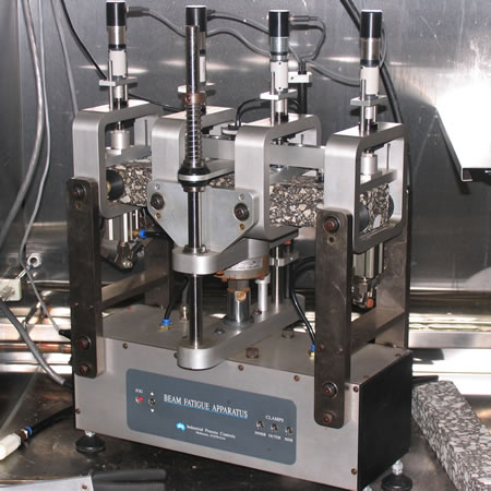
The basic flexural fatigue test subjects a HMA beam to repeated flexural bending in a controlled atmosphere (Figure 1). In order to relate laboratory results to normally observed field performance, a shift factor of 10 to 20 is typically needed. Because of the testing equipment complexity and long testing times, the flexural fatigue test is primarily a research test and is not a standard test in Superpave mix design or quality assurance testing.
The standard beam fatigue procedure is found in:
- AASHTO T 321: Determining the Fatigue Life of Compacted Hot-Mix Asphalt (HMA) Subjected to Repeated Flexural Bending
Background
In HMA pavements, fatigue cracking occurs when repeated traffic loads ultimately cause sufficient damage in a flexible pavement to result in fatigue cracking (Figure 2). A number of factors can influence a pavement’s ability to withstand fatigue, including pavement structure (thin pavements or those that do not have strong underlying layers are more likely to show fatigue cracking than thicker pavements or those with a strong support structure), age of the pavement, and the materials used in construction. The flexural fatigue test is used to investigate fatigue as it relates to HMA construction materials.

Fatigue Life Concept
The concept of a fatigue life centers around the universal idea that most materials undergo a gradual deterioration under repeated loads that are much smaller than the ultimate strength of the material. A paper clip can be broken by repeatedly bending it just as a large pressure vessel can fail after being subject to many thousands of pressure cycles. HMA pavements are similar.
A classic fatigue crack starts at the bottom of a HMA pavement layer (or structure) and grows towards the surface. It development is directly proportional to the strain level at the bottom of the layer (Carpenter, 2003[1]). This strain level changes with HMA thickness (thicker pavements give lower strain values), stiffness and other properties.
Endurance Limit
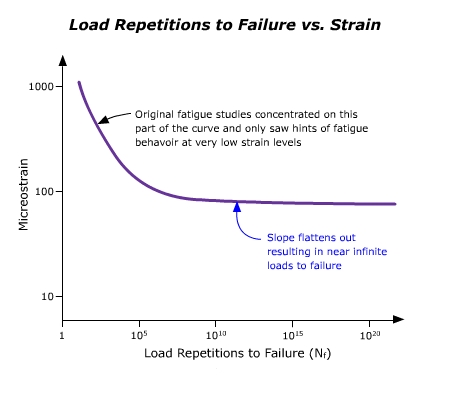
In 1970 Monismith et al. suggested that the relationship between strain at the bottom of the HMA layer and the number of cycles to failure seems to undergo a significant slope change at lower strain levels (in the vicinity of 70 microstrain). More recent studies seem to suggest that at low levels of strain (around 70 microstrain), HMA mixtures have, in effect, an infinite fatigue life. The theory is that a continuous physical-chemical healing reaction occurs, even during continuous loading, at low strain levels (Carpenter, 2003[1]). Therefore, a material property of HMA is its ability to recover some constant amount of damage or its “healing potential”. If damage due to loading falls below this “healing potential” then damage accumulation is virtually non-existent (Carpenter, 2003[1]). Typical plots of flexural strain vs. loads to failure tend to look like Figure 3. Note that beyond a certain point the plot is essentially horizontal – indicating an infinite fatigue life.
Work on NCHRP Project 9-38, Endurance Limit of Hot Mix Asphalt Mixtures to Prevent Fatigue Cracking in Flexible Pavements, is underway to identify the existence of a fatigue endurance limit and measure it for selected HMA mixtures.
Flexural Fatigue Test Principles
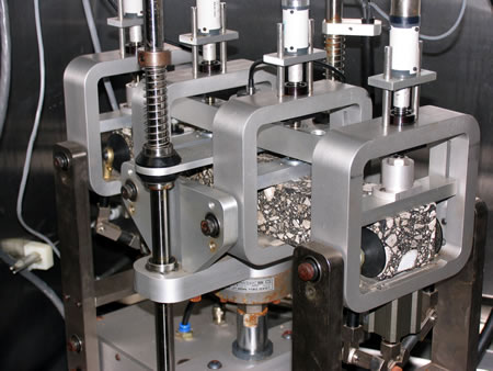
The flexural fatigue test is performed by placing a beam of HMA in repetitive four point loading at a specified strain level. During the test, the beam is held in place by four clamps and a repeated haversine (sinusoidal) load is applied to the two inner clamps with the outer clamps providing a reaction load (Figure 4). The load rate is variable but is normally set at 1 to 10 Hz. This setup produces a constant bending moment over the center portion of the beam (between the two inside clamps). The deflection caused by the loading is measured at the center of the beam. The number of loading cycles to failure can then give an estimate of a particular HMA mixture’s fatigue life. Another important value that can be obtained from the beam fatigue test is the dissipated energy of the specimen. Dissipated energy is a measure of the energy that is lost to the material or altered through mechanical work, heat generation, or damage to the sample.
Several key testing parameters require further explanation.
Constant Strain vs. Constant Stress
In recent years fatigue testing has been conducted using both constant stress or constant strain load applications. In constant strain mode the strain is maintained constant and the stress is allowed to vary. In constant stress mode the load is maintained the same and the strain is allowed to vary. Experience has shown that thick HMA pavements (> 5 inches (125 mm)) generally perform closer to a constant stress mode in the field, while thin HMA pavements (< 5 inches (125 mm)) generally perform closer to a constant strain mode in the field. Therefore, the constant strain mode favors more flexible mixtures and the constant stress mode favors stiffer materials. The constant strain mode is much more widely used because it appears to provide results that are more comparative to field observations.
Test Termination
The decision on when to terminate a flexural fatigue test depends on the test mode and purpose. For the constant stress mode, the test is continued until the beam actually breaks. For the constant strain mode, failure is more difficult to define because in order to keep the strain constant the applied stress is continually reduced, which results in a beam that never really breaks. Therefore, in constant strain mode, failure is normally defined as the point at which the load or stiffness reaches some predetermined value; most typically 50 percent of the original value.
Number of Tests
Typically it is not enough to perform only one isolated flexural fatigue test. Rather, a plot of multiple tests (typically a minimum of 10), each using a different load (for the constant stress mode) or different strain (for the constant strain mode) are produced (Kallas and Puzinauskas, 1972[2]). These plots can reasonably estimate a particular HMA mixtures stress vs. loads to failure or strain vs. loads to failure relationship. Other plots can also be generated.
Testing Temperature
Beam fatigue testing is performed at intermediate temperatures, usually 68°F (20°C), because fatigue cracking is thought to be a primary HMA distress at these intermediate temperatures. At higher in-service temperatures (above about 100°F (38°C)) rutting is usually the HMA distress of greatest concern, while at lower temperatures (below about 40 °F (4°C)) thermal cracking is usually the HMA distress of greatest concern.
Test Description
The following description is a brief summary of the test. It is not a complete procedure and should not be used to perform the test. The complete test procedure can be found in:
- AASHTO T 321: Determining the Fatigue Life of Compacted Hot-Mix Asphalt (HMA) Subjected to Repeated Flexural Bending
Summary
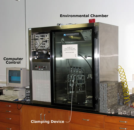
Small HMA beams (15 x 2 x 2.5 inches (380 x 50 x 63 mm)) are made and placed in a 4-point loading machine, which subjects the beam to a repeated load. Tests can be run at a constant strain level or at a constant stress level. Figure 5 shows the major test equipment.
Approximate Test Time
Testing time is dependent on the strain level chosen for the test. High strain (400 – 800 microstrain) may be completed in a few hours. Low strain tests (200 – 400 microstrain) can take several days. Even lower strain levels (50 – 100 microstrain) can take upwards of a month. Typically 8 to 10 samples are used to develop results for any mix. Hence, it may take several days to several weeks to develop sufficient fatigue data to allow analysis of a given mixture.
Basic Procedure
- Obtain a test beam by sawing at least 0.25 inches (6 mm) from both sides of a compacted HMA specimen. The final dimensions should be 15 inches (380 mm) length by 2 inches (50 mm) height by 2.5 inches (63 mm) width (Figure 6).

- Prepare three replicate beams. If these are laboratory-prepared or loose field samples, compact them in accordance with AASHTO PP 3 or ASTM D 3202. These compaction procedures describe the use of a linear kneading compactor (rather than a SGC) to compact square (rather than cylindrical) samples. If these are already-compacted samples obtained from the roadway, they need not be compacted in the laboratory.
- Measure the height and width of each beam to the nearest 0.0004 inch (0.01 mm) at three points along the middle 4 inches (100 mm) of the beam and determine the average for each dimension.
- Condition the beams at the test temperature (typically 68°F (20°C)) for two hours
- Open clamps and slide specimen into position. Close outside clamps first, then inside clamps with enough pressure to hold the specimen in place (Figure 7).
- Position the LVDT onto the specimen such that the LVDT displacement reading is close to zero.
- Allow sample to rest for 10 minutes to relax any residual stresses caused by loading.
- Select an initial strain (250 – 750 microstrain), loading frequency (5 – 10 Hz), and interval at which the results should be recorded and enter them into the control components of the test program.
- Apply 50 load cycles and determine the beam stiffness at the 50th cycle. This will be recorded as the initial stiffness of the beam.
- Select a strain level that will provide an estimated 10,000 load cycles before the initial stiffness is reduced to 50 percent or less.
- Begin the test. Test results should be monitored and recorded at the selected load cycle intervals and the test should be terminated when the beam has reached a 50 percent reduction in stiffness. It is possible that very low strain tests may not reach the 50 percent reduction in stiffness in a reasonable amount of time. In this case a maximum number of cycles should be specified as the termination point of the test.
Results
Parameters Measured
The beam fatigue test provides a measure of the fatigue life and fatigue energy of HMA pavements. To do this it can measure or calculate the following parameters:
- Maximum tensile stress
- Maximum tensile strain
- Flexural stiffness
- Phase angle
- Dissipated energy per cycle
- Cumulative dissipated energy
- Initial stiffness
- Number of cycles to failure
- Cumulative dissipated energy to failure
Specifications
There is currently no specification associated with this test procedure. The flexural fatigue test is essentially a research test and is not used in specifications.
Calculations (Interactive Equation)
Calculations of maximum tensile stress, maximum tensile strain, stiffness and dissipated energy are made periodically (every load repetition, every 10th repetition, every 100th repetition, etc.).
Maximum Tensile Stress
![]()
Where:
- σt = maximum tensile stress (Pa)
- a = space between inside clamps (0.119 m)
- P = applied load (N)
- b = average beam width (m)
- h = average beam height (m)
Maximum Tensile Strain
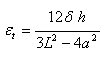
Where:
- εt = maximum tensile strain (m/m)
- δ = applied load (N)
- h = average beam height (m)
- L = beam length between outside clamps (0.357 m)
- a = space between inside clamps (0.119 m)
Flexural Stiffness

Where:
- S stiffness (Pa)
- σt = maximum tensile stress (Pa)
- εt = maximum tensile strain (m/m)
Phase Angle
![]()
Where:
- φt = phase angle (degrees)
- f = load frequency (Hz)
- s = time lag between maximum load and deflection (s)
Dissipated Energy per Cycle
![]()
Where:
- D = dissipated energy per cycle (J/m3)
- σt = maximum tensile stress (Pa)
- εt = maximum tensile strain (m/m)
- φt = phase angle (degrees)
The cumulative dissipated energy is then the sum of the dissipated energy for each load cycle.
- Carpenter, S. (2003). Perpetual Pavement: Laboratory Validation. Presentation at the 57th Annual Ohio Transportation Engineering Conference.http://www.otecohio.org/presentations/OTECpresentations/Se20/Carpenter-OHIOFatigue.pdf. Accessed 8 December 2004.↵
- Kallas, B.F. and Puzinauskas, V.P. (1972). Flexural Fatigue Tests on Asphalt Paving Mixtures. Fatigue of Compacted Bituminous Aggregate Mixtures. American Society of Testing and Materials (ASTM), STP 508.↵