Introduction
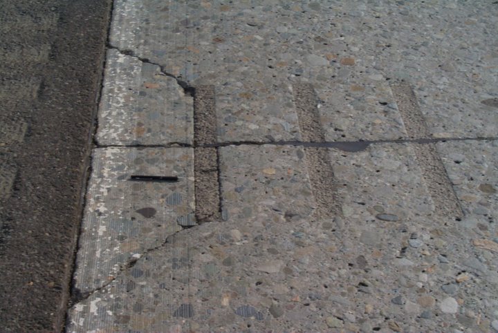
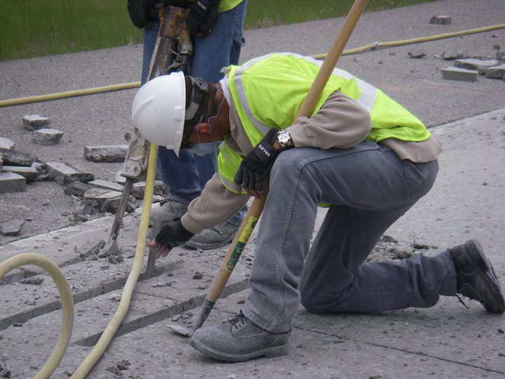
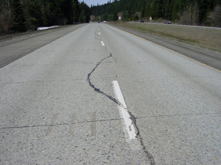
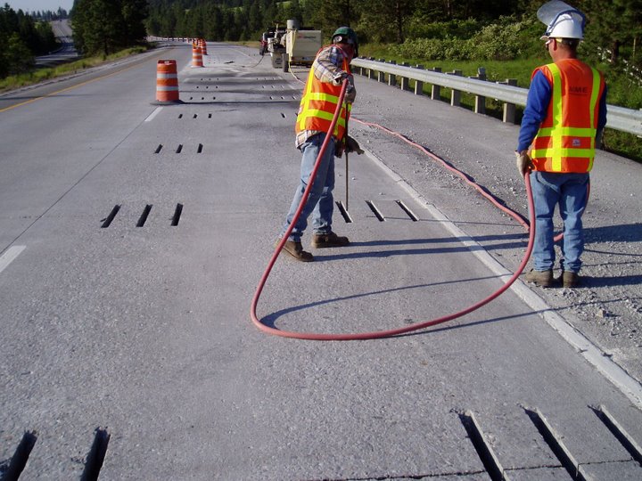
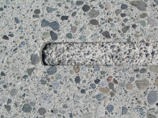
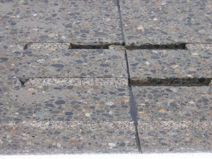
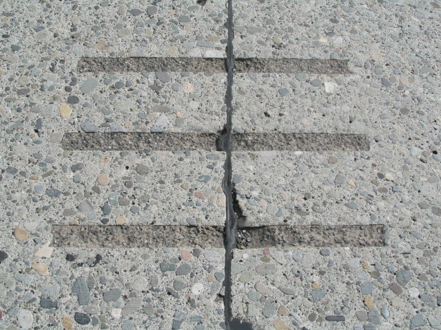
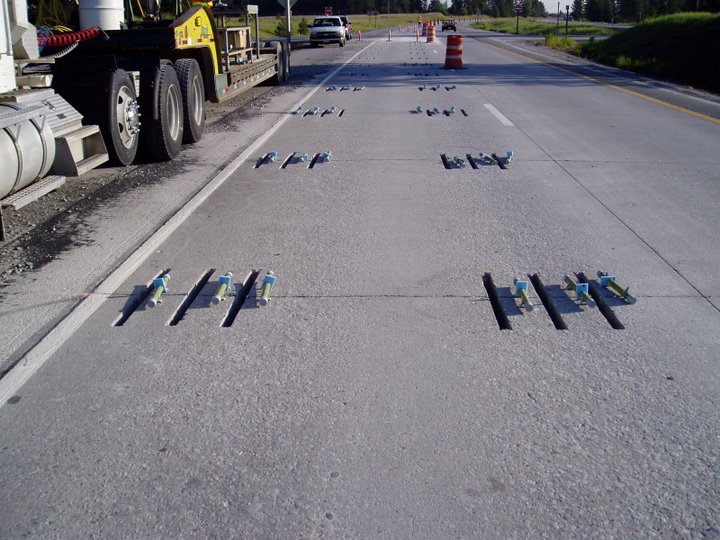
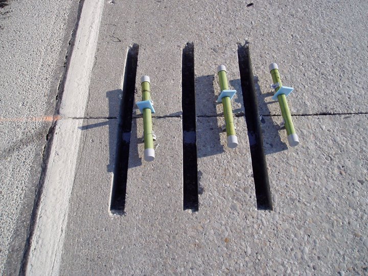
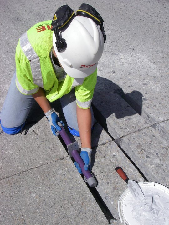
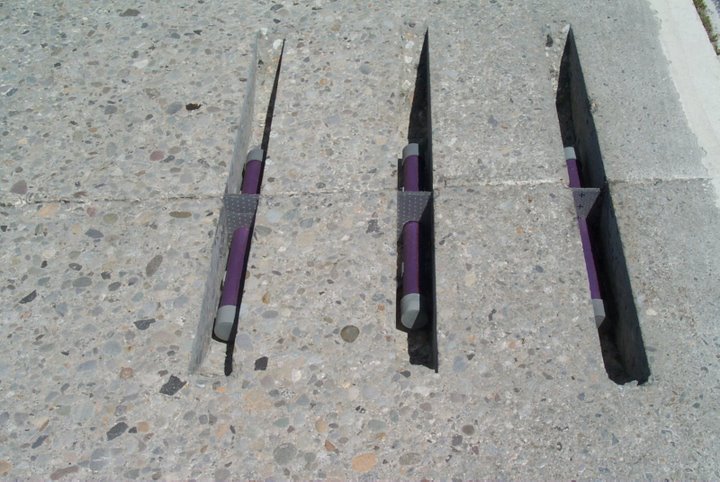
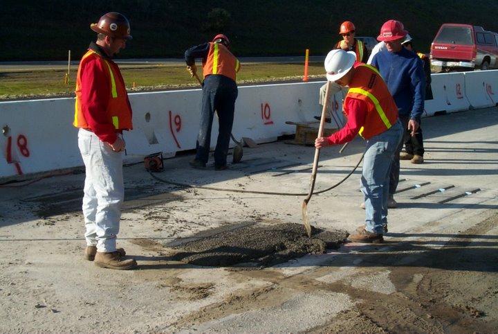
The following describes and illustrates the dowel bar retrofit construction process. In addition, descriptions of critical details for ensuring pavement performance are also included.
In general, the dowel bar retrofit process includes the following steps:
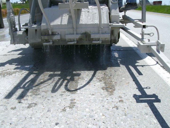
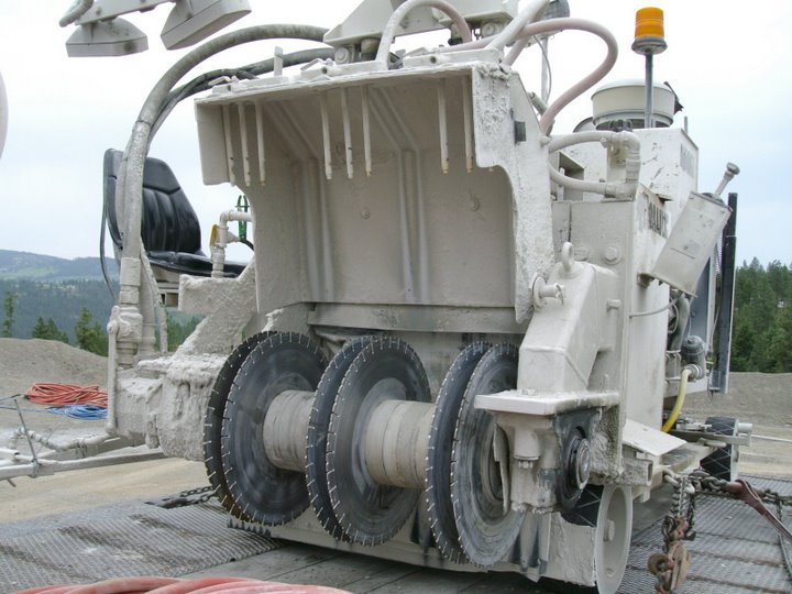
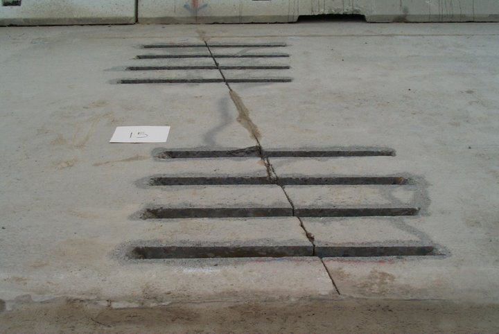
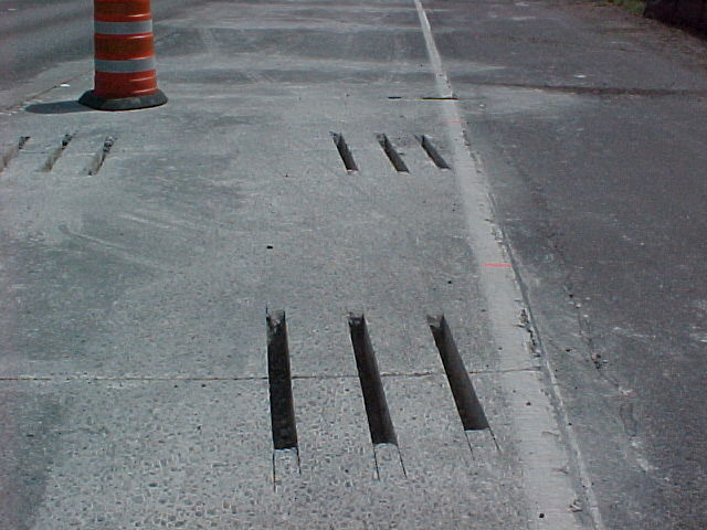
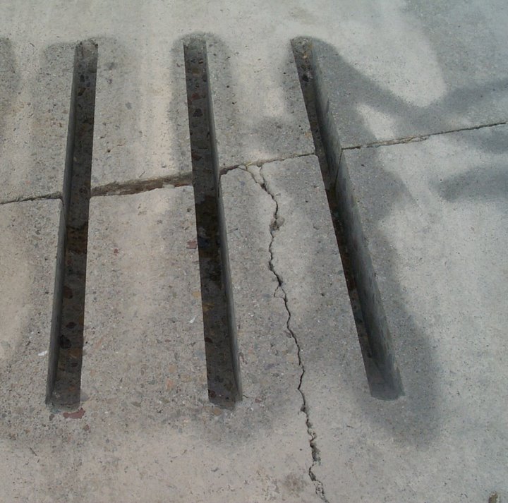
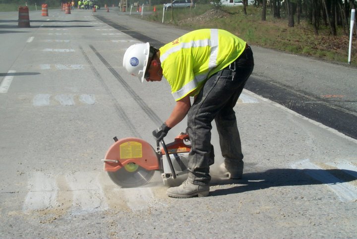
- Using diamond saw blades, sawcut dowel bar slots (three to four per wheelpath).
- Remove existing concrete within dowel bar slot.
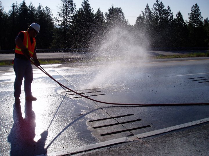
- Remove diamond blade slurry and other debris from dowel bar dowel bar slot.
- Seal existing the joint or crack within the dowel bar slot with caulking material.
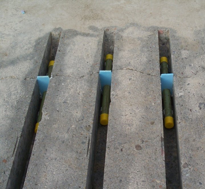
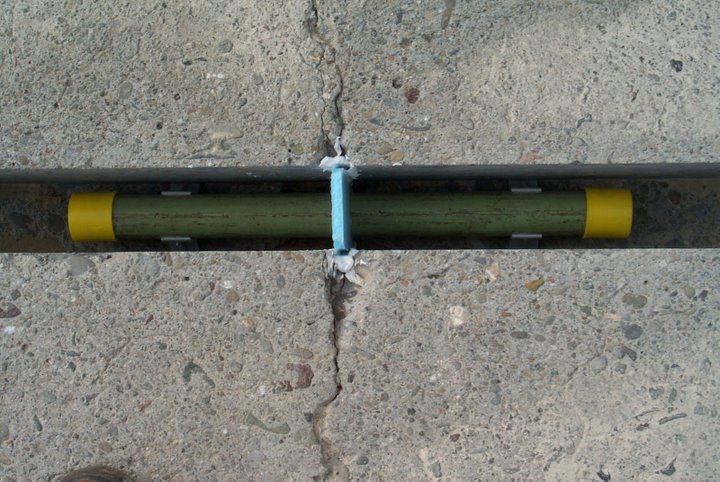
- Place dowel bar assembly (dowel bar, chairs and end caps) into the dowel bar slot, centered over the joint or crack.
- Place, consolidate and cure patching material.
- Diamond grind surface.
Since dowel bar retrofit performance is highly dependent on construction practices, it is advised that prior to project startup the project inspector consider the following:
- Familiarization of Construction Plans, Specifications and Special Provisions
- Consider preconstruction workshop to ensure contractor and agency understand project requirements
- Consider including experienced personnel during the preconstruction meeting and potentially on the job-site during construction.
- Bridge approach slabs should not be retrofitted.
Dowel Bar Retrofit and Panel Replacement Guidelines
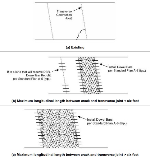
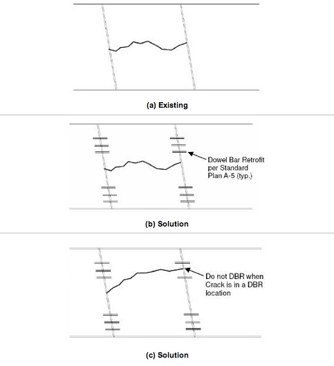
The following images illustrate general guidelines for applying dowel bar retrofit and panel replacements.
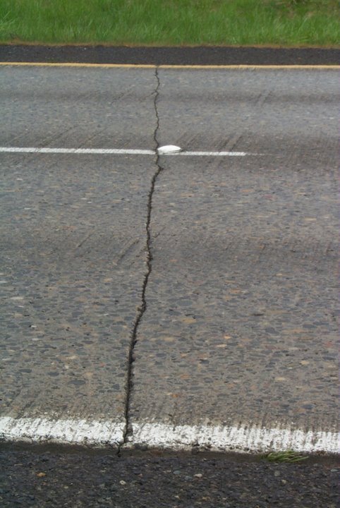
Transverse Crack

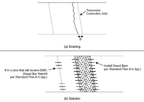
Transverse Working Crack


Multi-Cracked and Settled Slabs
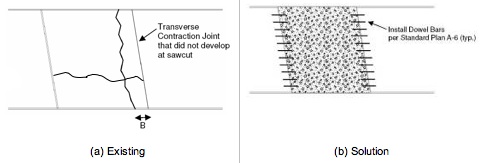
Corner Crack

Cutting Dowel Bar Slots
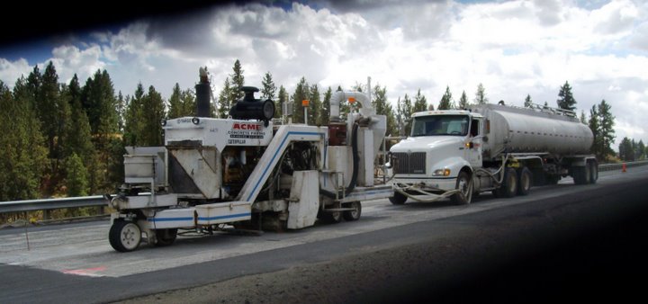
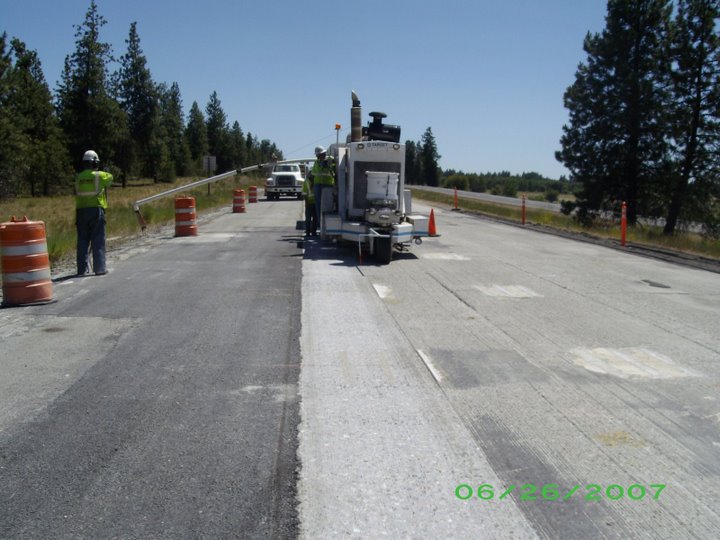
Figure 9 illustrates equipment that can saw cut six dowel bar slots in one pass. This device is very effective in cutting both non skewed and skewed transverse joints. This device is also effective in cutting dowel bar slots on transverse cracks, depending on angle of crack skew.
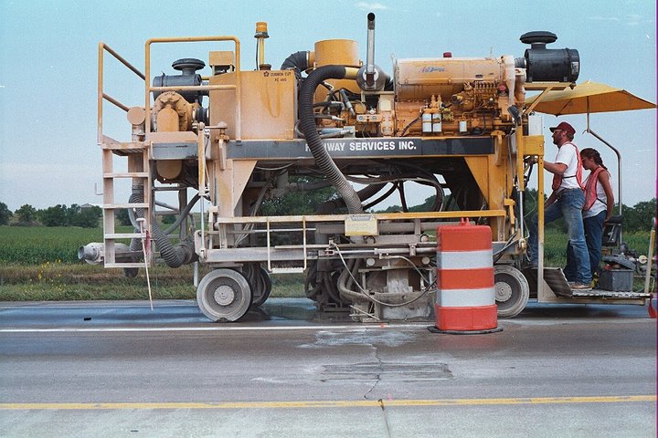
Figure 10 and Figure 11 shows the three dowel bar slots per wheelpath equipment. This equipment is effective in cutting dowel bar slots on both non-skewed and skewed joints and transverse cracks.
|
|
|
Figure 12 illustrates equipment to saw cut a single dowel bar slot
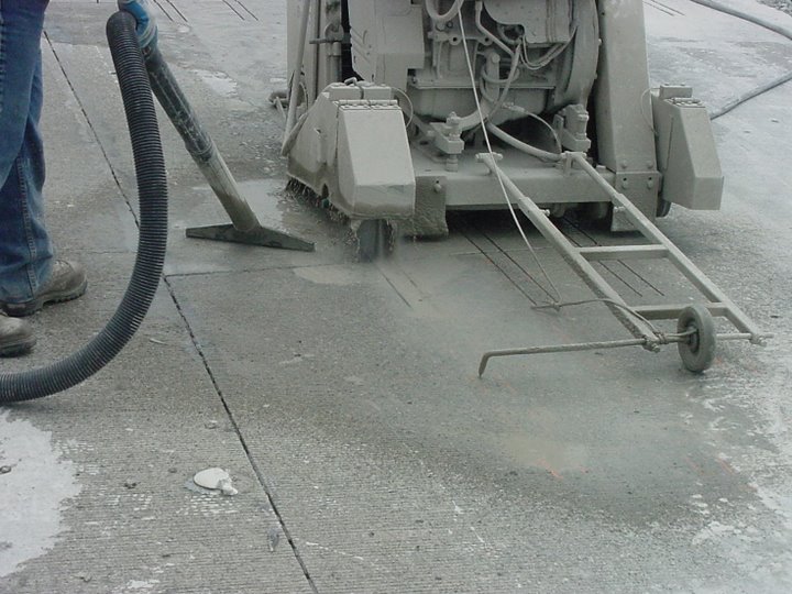
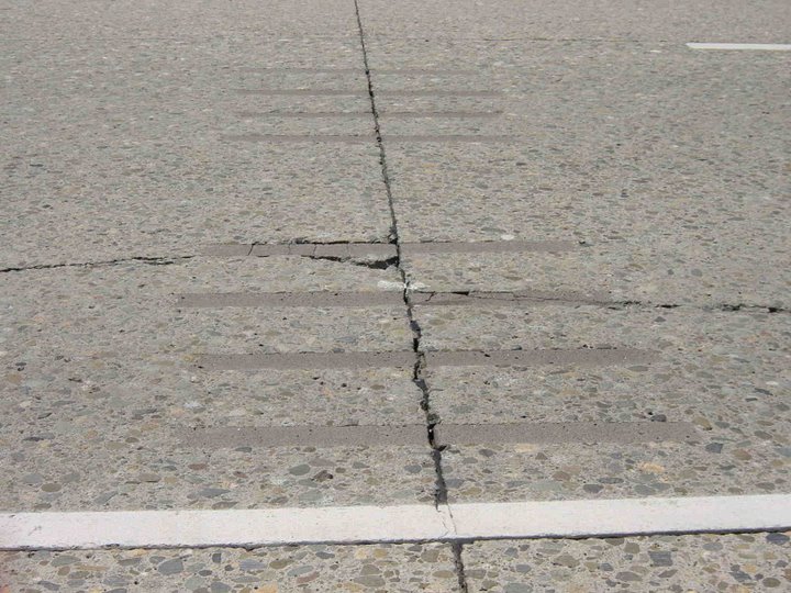
Figure 13 illustrates the completed sawcutting operation on a non-skewed transverse joint.
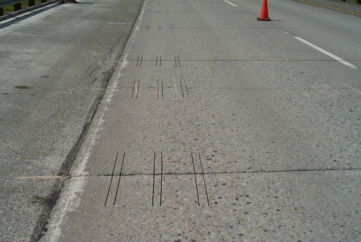
For skewed joints, when using sawcutting equipment that is capable of cutting three or more dowel bar slots per wheelpath or six dowel bar slots per joint (in one pass), dowel bar slots should be cut with sufficient length (Figure 14) to allow the dowel bar assembly to be centered over the joint (equal length of dowel bar on either side of the joint).
Proper alignment of the dowel bar slot is essential for minimizing the potential for dowel bar lockup. Lockup is the inability of the dowel bar to move freely as the slab expands and contracts due to curling and warping. If the dowel bar movement is restricted, stresses can be induced within the dowel bar slot and eventual cracking and spalling of patching material may occur. Stresses may also be significant to cause cracking within the concrete panel.
Figure 15 illustrates dowel bar slots that have not been correctly sawcut on a skewed joint. In this case, the dowel bar slots were cut perpendicular to the skewed joint (as is necessary for non-skewed joints) rather than parallel to centerline.
|
|
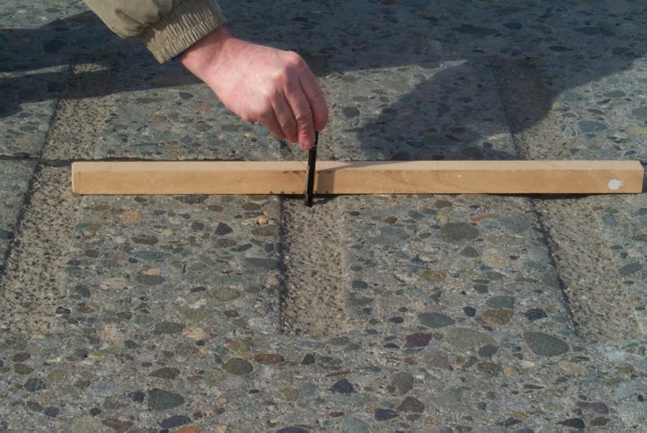
Slots cut deeper than necessary can contribute to corner cracking (Figure 16) and patching material failure and the potential of the jackhammer punching through the bottom of the dowel bar slot. The Contractor/Inspector should physically measure (Figure 17) the dowel bar assembly height (including chairs) to ensure proper sawcut depth.
Dowel bar slot width should also be confirmed to ensure that the dowel bar chairs and foam core board fit snugly against the sides of the dowel bar slot. This will assist in holding the dowel bar assembly securely in the dowel bar slot during placement of the patching material.
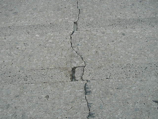
Dowel bar slots should be aligned to miss (Figure 18) any existing longitudinal crack. Depending on the wander of the longitudinal crack, dowel bar slots could also be eliminated (Figure 19). If the longitudinal crack was located in the right wheelpath, completely eliminating all dowel bar slots would not be recommended. In this instance, it may be best to place as many dowel bar slots as possible without intersecting the longitudinal crack.
Figure 20 through Figure 21 illustrates instances where the dowel bar slot was not placed to miss the existing longitudinal crack resulting in failure of the patching material. Dowel bar slots placed over a longitudinal crack will fail (Figure A-20) within a very short period of time (< 12 months). The failure mechanism is typically debonding, cracking and spalling of the concrete patching material. Shifting dowel bar slots, three to four inches, will prevent this distress while still providing the required load transfer. If a gang saw is used, dowel bar slots may be sawed but not retrofitted, any non-retrofitted sawcuts should be cleaned and sealed with an epoxy resin.
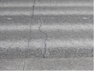
All existing transverse joints and cracks should be dowel bar retrofitted. Figure 22 shows a non-working joint (narrow joint opening and excellent joint sealant condition after being in-service for more than 20 years with no maintenance) and a transverse crack that is functioning as the working joint. In this case, the crack should be dowel bar retrofitted and not the joint.
Removing Existing Concrete from Dowel Bar Slots
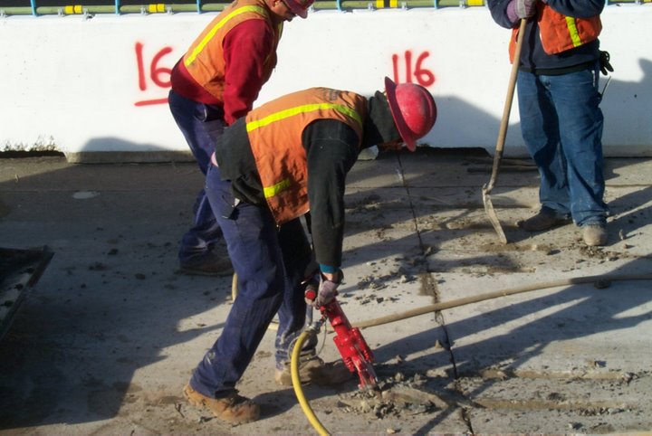
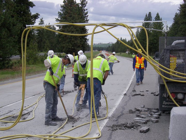
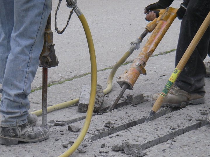
The existing concrete should be removed from the dowel bar slot using jackhammers weighing 30 pounds or less. Jackhammers should be operated at a 45 degree angle or less (Figure 23 through Figure 25). Jackhammers operated in a vertical position can punch through the bottom of the dowel bar slot.
|
|
Leveling of the dowel bar slot bottom (Figure 26) helps ensure that the dowel bar will meet alignment tolerances. This work should be conducted with a 15-pound or lighter jackhammer.
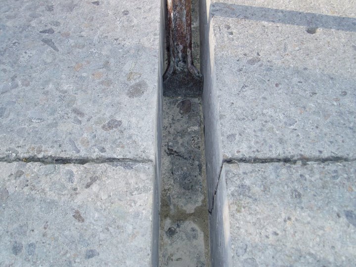
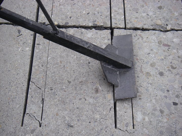
A breaker bar (Figure 27 and Figure 28) may be used to expedite the jackhammer removal operation of the concrete within the dowel bar slot.
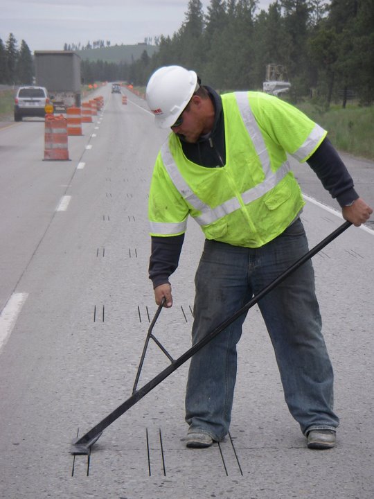
Figure 29 illustrates insufficient removal of the existing concrete from the bottom of the dowel bar slot. This high point may result in a skew in the horizontal position of the dowel bar beyond that which is allowed by specification tolerances. If this skew is severe, dowel bar lockup and eventual failure of the patching material may occur. Slot bottom should be leveled using a lightweight (< 15 pound) jackhammer.
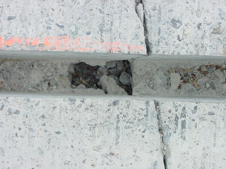
Figure 30 illustrates insufficient removal of the existing concrete at the end of the dowel bar slot. Improper concrete removal could result in insufficient length for the dowel bar to sit level in the dowel bar slot and may not allow for sufficient patching material around the dowel bar. Though this may not be extreme in this case, spalling at the end of the dowel bar slot may occur due to difficulty in obtaining patching material consolidation.
Figure 31 illustrates a situation where the jackhammer operation caused failure of the bottom of the dowel bar slot. This may have occurred due to operating the jackhammer at an angle greater than 45 degrees, the dowel bar slot was sawcut to deep leaving an insufficient depth of concrete between the dowel bar slot bottom and the bottom of the concrete slab, which was easily broken during the jackhammering process or the use of jackhammers weighing more than 30 pounds.
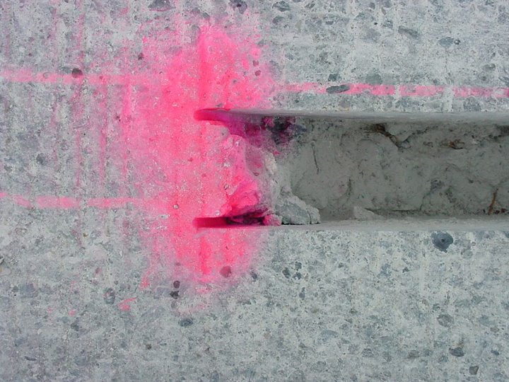
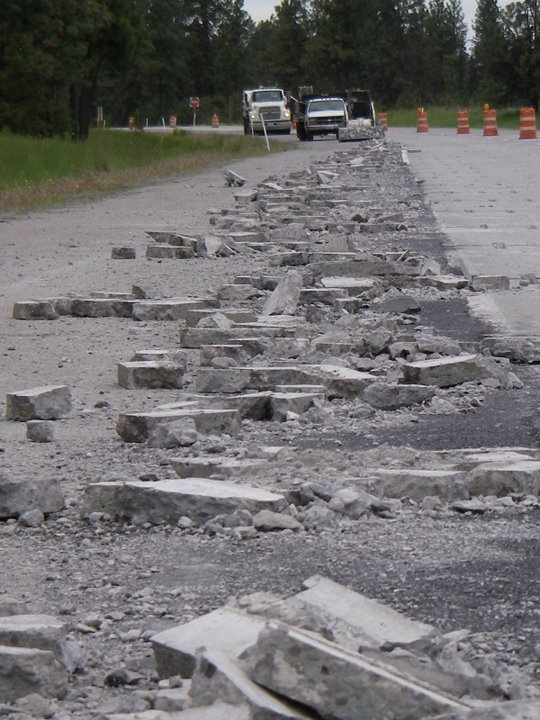
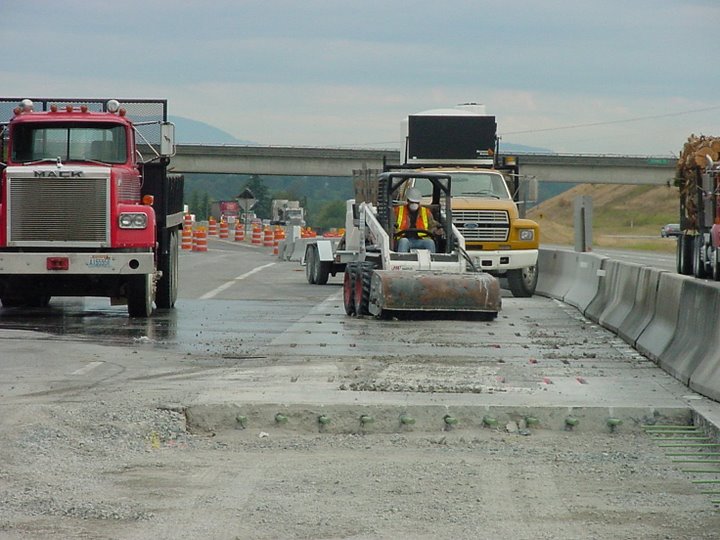
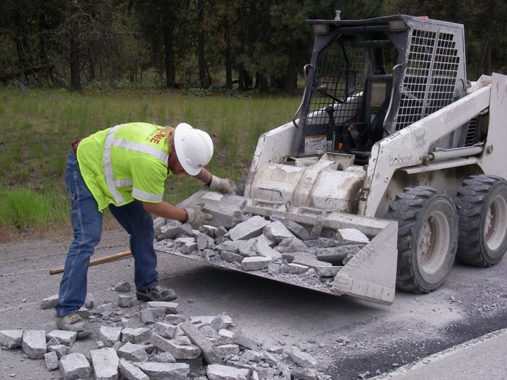
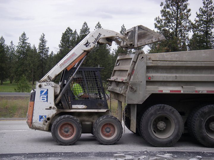
Removal of the dowel bar slot debris from the jackhammering operation can be quite laborious. The use of a small loader can aid in the clean-up operation (Figure 32 through Figure 35).
|
|
Cleaning Dowel Bar Slots
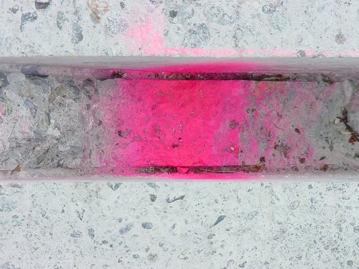
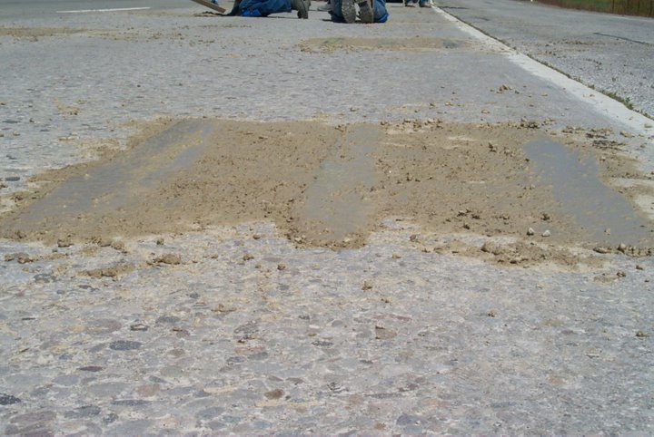
After completion of the sawcutting and concrete removal process, debris and saw blade slurry exists in the dowel bar slot (Figure 36). This material must be removed prior to installation of the dowel bar assembly. Insufficient cleaning of the dowel bar slot will prohibit adherence of the patching material to the existing concrete, which will result in a bonding failure between the patching material and the existing concrete.
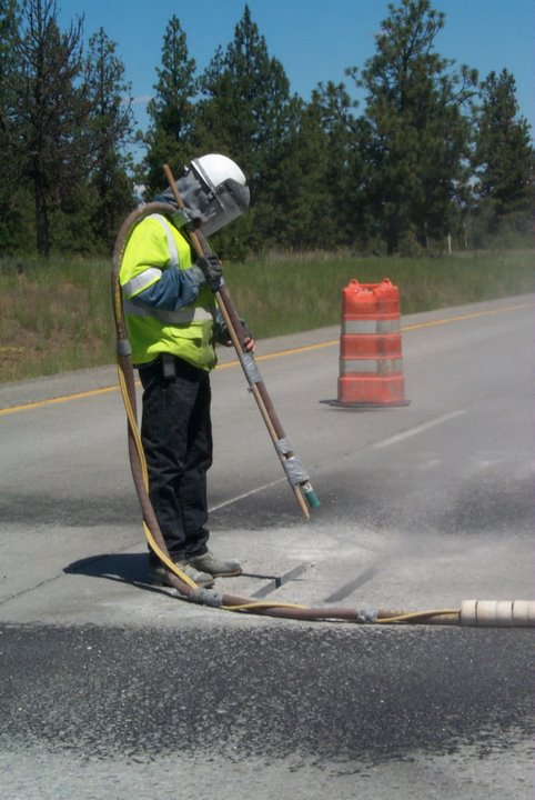
All exposed surfaces and cracks in the dowel bar slot should be sand blasted (Figure 37 and Figure 38) and cleaned to bare concrete to remove any diamond saw blade slurry or other debris. The dowel bar slot is considered to be clean when all debris and standing water has been removed from the dowel bar slot sides and bottom. The side of the dowel bar slot is considered clean when wiping the sides of the dowel bar slot, with a clean towel or hand, produces no residue.
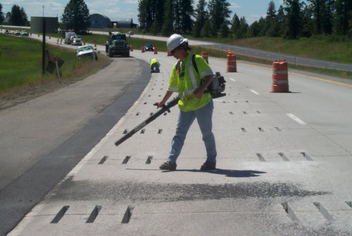
Compressed air (Figure 40 and Figure 41) may also be used to remove debris, water and slurry from the sides and the bottom of the dowel bar slots.
|
|
Figure 42 shows a properly cleaned dowel bar slot.
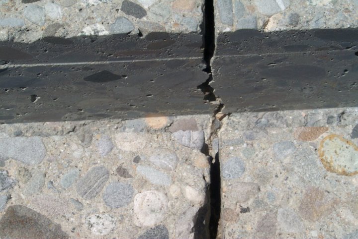
Removal of debris and slurry residue can be challenging if water is present in the dowel bar slot. If water is present (Figure 43), slurry residue is redistributed to the bottom or sides of the dowel bar slots by sandblasting or compressed air. More than one attempt at cleaning the dowel bar slot may be required in obtaining the desired cleanliness.
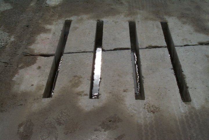
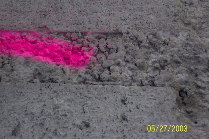
Figure 44 and Figure 45 shows debonding of the patching material from the dowel bar slot. This distress is typically related to inadequate cleaning of the dowel bar slot. Repair of this distress requires removal and replacement of the patching material.
Figure 46 illustrates spalling of the patching material. Potential causes of this distress can be related to consolidation, lack of sufficient aggregate or opening too early to traffic. Figure 47 illustrates insufficient consolidation in the patching material. Repair, for both instances would include removal and replacement of two to three inches in depth of the patching material.
Figure 48 illustrates shrinkage cracking of the patching material. This type of cracking is repaired by removal and replacement of distressed patching material.
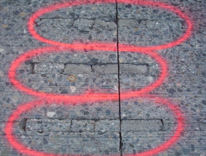
Debris should be removed to a minimum of four feet from the dowel bar slots. This material can be reintroduced (Figure 49) into the dowel bar slot and may result in bonding issues.
Sealing Joint or Crack within the Dowel Bar Slot
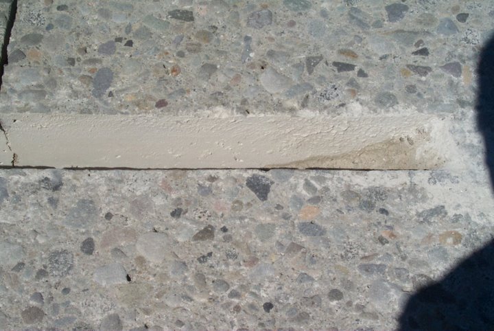
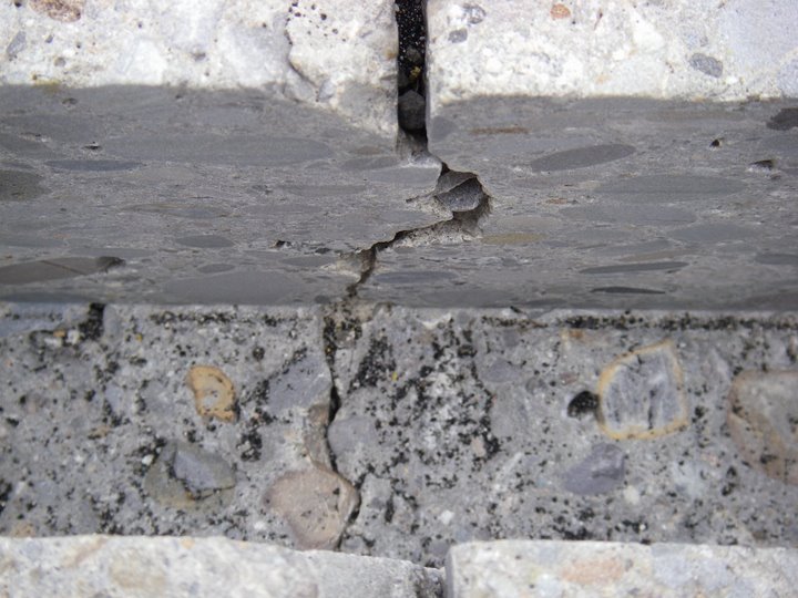
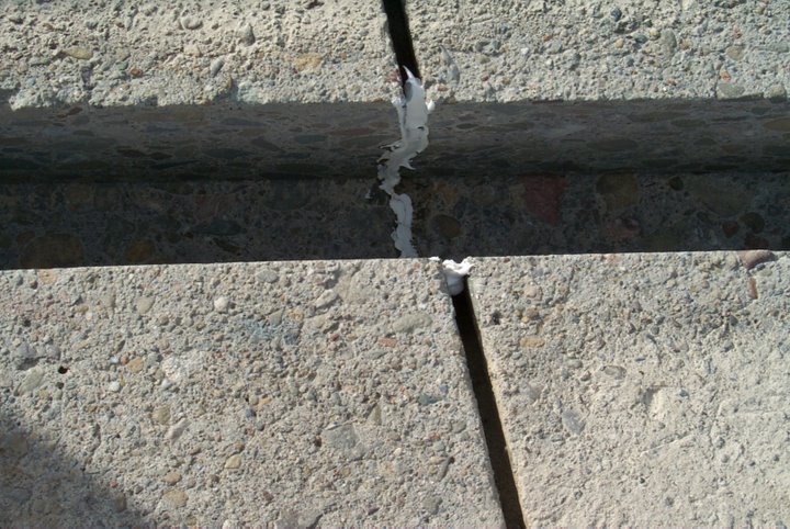
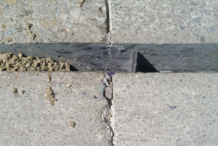
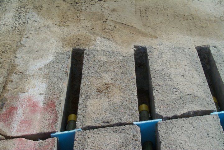
Transverse joints and cracks must be caulked (Figure 50 and Figure 51) within the dowel bar slot. Caulking material should not extend more than ½ inch beyond either side of the joint or crack. The caulking material will prevent patching material from entering the joint/crack.
Placement of Dowel Bar Assembly
Prior to assembly and placement into the dowel bar slot, dowel bars should be lightly coated with a parting compound. Parting compound that is applied after the dowel bar assembly has been placed in the dowel bar slot will result in debonding of the patching material. Once the parting compound has been applied, foam core board, chairs and end caps should be installed onto the dowel bar.
The chair design should hold the dowel bar tightly and fit snugly against the dowel bar slot such that movement is minimized during placement of the patching material. Chairs should be strong enough to allow full support of the dowel bar. Chairs should allow at least a ½ inch clearance between the bottom of the dowel and the bottom of the dowel bar slot.
End caps shall be tight fitting, placed on each end of the dowel bar, each allowing at least ¼ inch of movement. Loose fitting end caps will allow movement of the dowel bar within the dowel bar slot, which could lead to failure of the patching material. The dowel bar must be allowed to move within the end cap to allow for expansion and contraction due to curling and warping.
The ⅜ inch thick foam core board (closed cell foam with plastic or poster board faced material) should be of sufficient quality to allow a tight fit around the dowel bar and to all edges of the dowel bar slot during placement of the patching material. Care should be given to ensure the foam core board extends beneath the dowel bar to the bottom of the dowel bar slot. The foam core board should be placed at the transverse joint or transverse crack and at the middle of the dowel bar. The foam core board reestablishes the transverse joint or crack and allows for the expansion of the patching material.
Dowel bars assemblies must be centered over the existing transverse joint or transverse crack and parallel to the concrete surface.
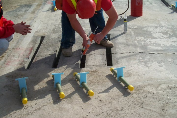
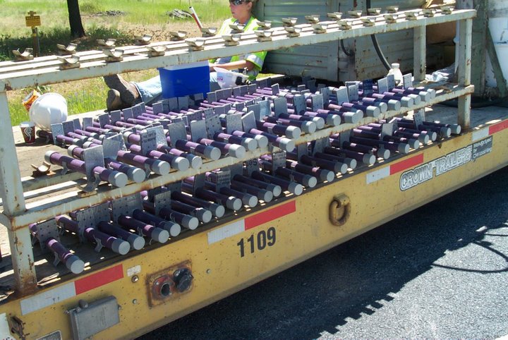
Figure 52 shows the assembled dowel bars, chairs, end caps and foam core boards on a flat bed trailer. Dowel bar assemblies are taken from the flat bed trailer, placed adjacent to the dowel bar slot locations (Figure 53 and Figure 54) and inserted into the dowel bar slot (Figure 55). Figure 56 shows the dowel bar assembly at a transverse joint location and Figure 57 and Figure 58 shows the dowel bar assembly at transverse cracks.
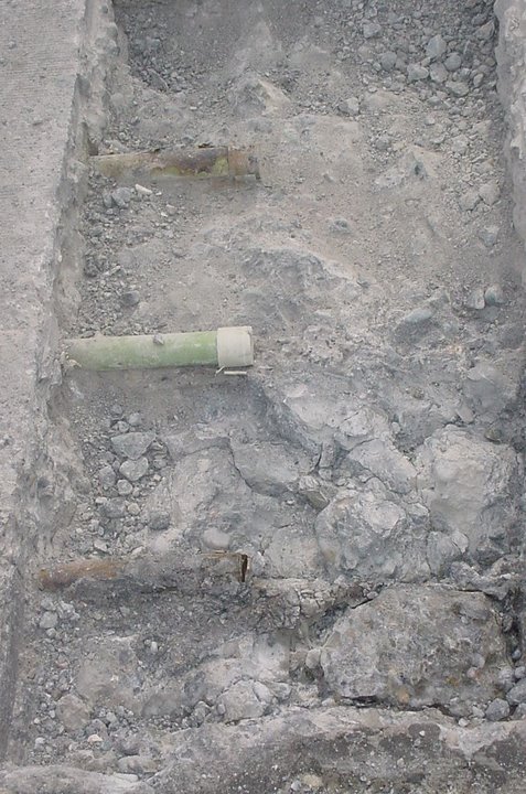
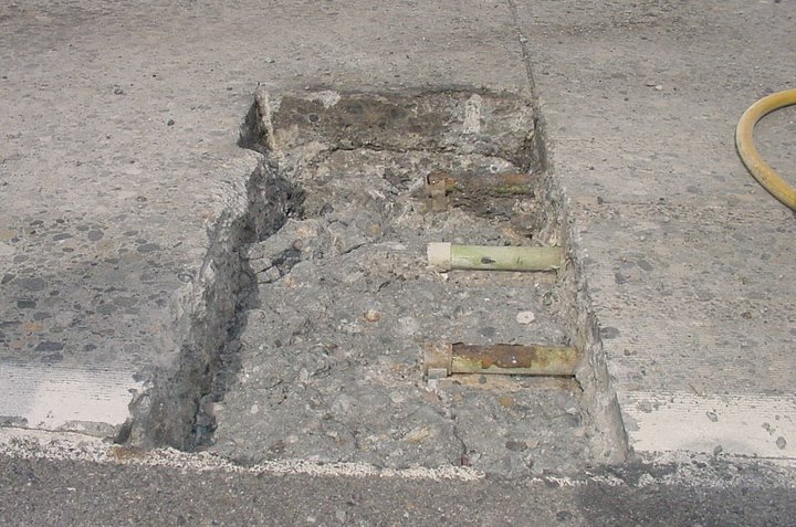
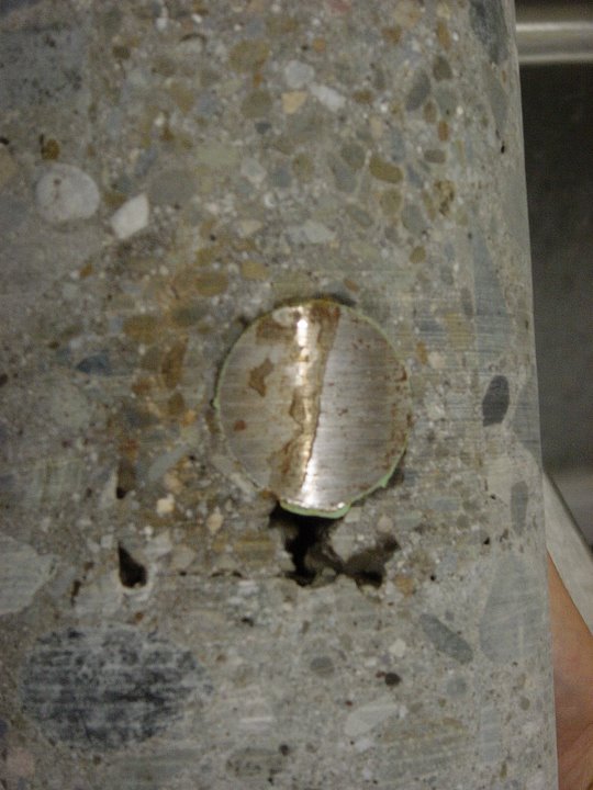
Prior to installation, the dowel bar epoxy coating should be inspected and if any discrepancies are present the dowel bar should be rejected. On one dowel bar retrofit failure, dowel bar corrosion (Figure 59 and Figure 60) was determined to be the cause of the dowel bar slot failure.
Placement of Patching Material
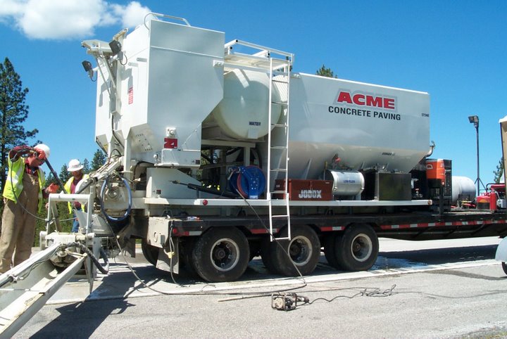
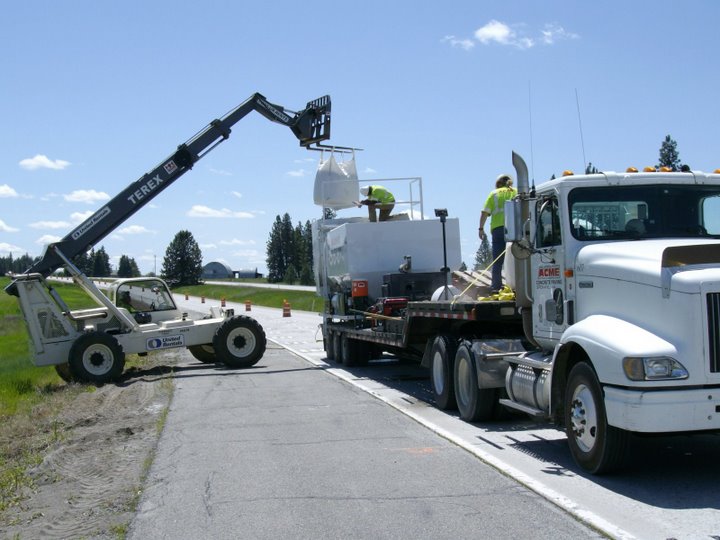
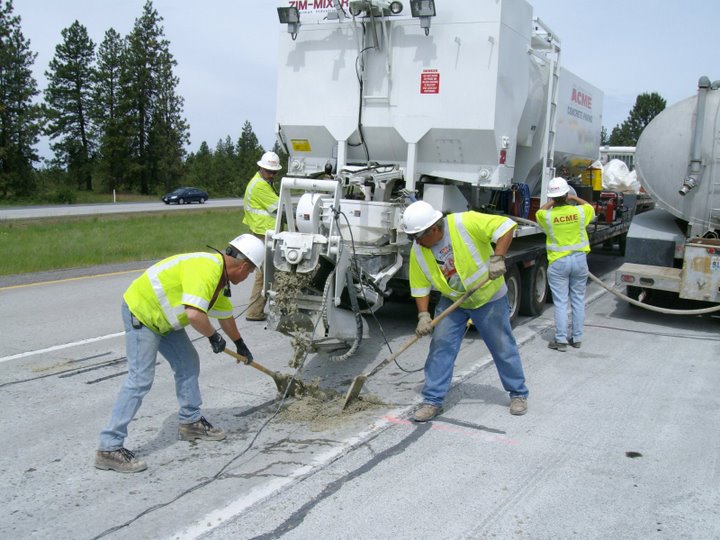
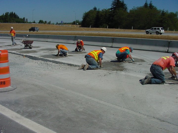
Patching material can be batched using a mobile mixer (Figure 61 and Figure 62) or in individual batches. If a mobile mixer is used, batching of the individual components must be closely monitored to ensure proper proportioning.
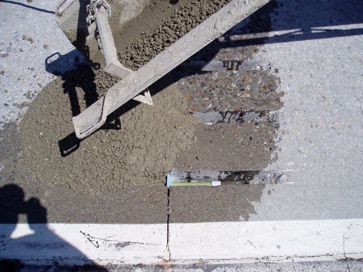
Patching material should not be dumped directly into the dowel bar slot; the impact of the patching material falling directly into the dowel bar slot will cause movement of the dowel bar assembly. The patching material should be placed adjacent (Figure 63 and Figure 64) to and spread with shovel (Figure 65) toward and into the dowel bar slot.
Placement of patching material that causes movement (Figure 66 and Figure 67) of the dowel bar assembly should be rejected and replaced.
Patching material consolidation should be conducted with a pencil (or similar) vibrator (Figure 68). Care must be taken to not relocate the dowel bar assembly during consolidation.
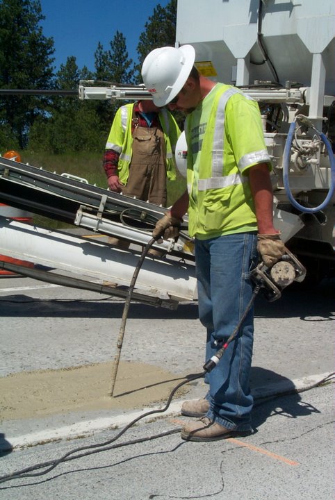
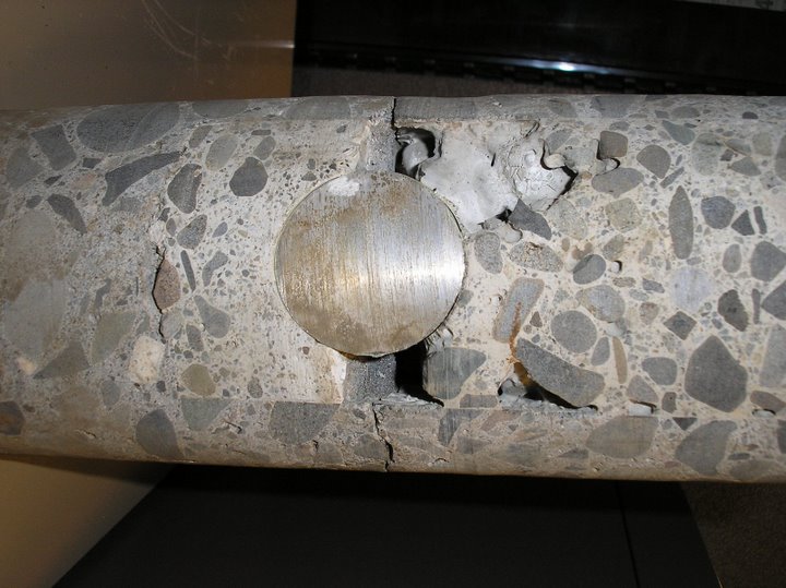
Figure 69 and Figure 70 illustrate patching material voids in the vicinity of the dowel bar. The core shown in Figure 69 was taken from the first dowel bar retrofit project and illustrates lack of consolidation beneath the dowel bar, which could be due to aggregate size and the inability to move the aggregate around the dowel bar or lack of consolidation. Figure 70, on the other hand, was taken from a more recent project (2006) and shows lack of consolidation around and above the bar. In this case, it was determined that the aggregate gradation was too large to adequately fit around the bar and WSDOT modified specifications to allow only AASHTO Grading No. 8 (prior to this project, either AASHTO Grading No. 7 or 8 was allowed).
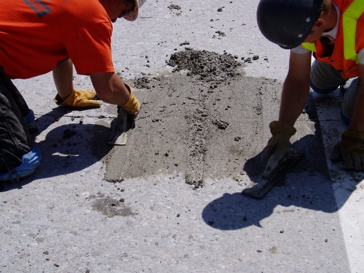
During the finishing process, care should be taken to not overwork the patching material (Figure 71 and Figure 72). Overworking can lead to segregation and floating of the fine material to the surface of the dowel bar slot. The fine material is susceptible to wear, especially when subjected to studded tires. Patching material should be left ⅛ inch to ¼ inch high (Figure 73 and Figure 74), which will be removed during the diamond grinding process.
|
|
|
Curing compound should be applied (Figure 75) to the patching material as soon as possible after the finishing operation.
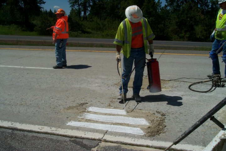
Establishing the transverse joint within the dowel bar slots (Figure 76) should be conducted within 24 hours after placement. If the transverse joints were originally constructed with a tape joint and the joint is uneven (Figure 77), the transverse joint should not be sawcut. In this situation, sawcutting a straight line would be challenging without creating slivers that would eventually spall.
Figure 78 illustrates damage caused by mechanically sweeping the roadway prior to the patching material reaching the required strength. As before, the methodology for repairing this distress is to saw cut, remove and replace two to three inches of the distressed material.
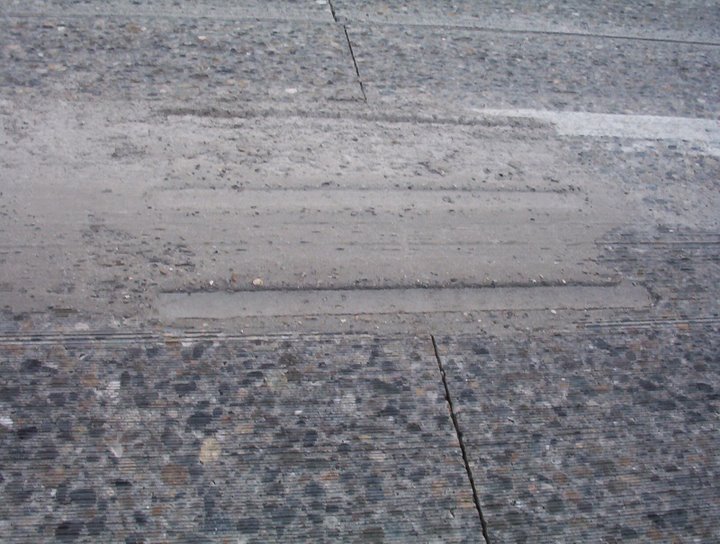
Studded tire wear is one of the more predominant distresses affecting pavement (both HMA and concrete) performance in Washington State. For dowel bar retrofit, the largest impact of studded tires is wear in the dowel bar slot (Figure 79 and Figure 80).
Diamond Grinding
Diamond grinding (Figure 81 through Figure 83) should begin within 10 working days of placing dowel bar retrofit patching materials. The primary reason for this specification is to minimize traveler complaints related to intentionally leaving dowel bar patching material high.
Slurry Removal
Removal of the grinding residue from the roadway surface should occur immediately after grinding. Slurry should not be allowed to drain across open traffic lanes and shoulders. Slurry should not be allowed to drain into any waterway, placed on the roadway slope within 200 feet of any waterway, or other areas as designated by the Engineer.
The agencies environmental section should be consulted during the dowel bar retrofit design regarding concrete slurry removal. Some projects will allow slurry to be placed on the roadway slopes while some areas, depending on environmental requirements, will require that the slurry be deposited (and treated as necessary) off site.
Reseal Joints and Cracks
Research studies have been conducted for determining the benefits of resealing concrete joints. There will be no attempt to determine the economic benefits of joint resealing in this document, however, it is recommended that all joints and cracks be cleaned and sealed following the diamond grinding process. The primary reasons are to remove any debris and diamond grinding slurry from joints and cracks and to minimize the amount of water and incompressibles from entering the pavement structure through the joints and cracks.
Completed Product
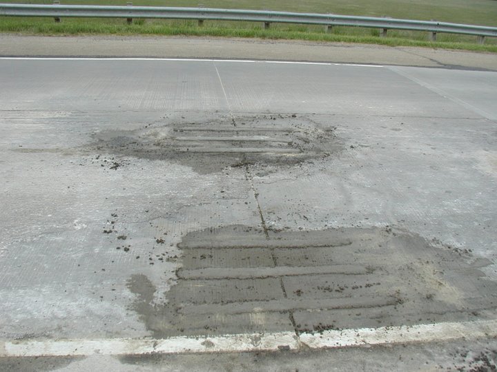
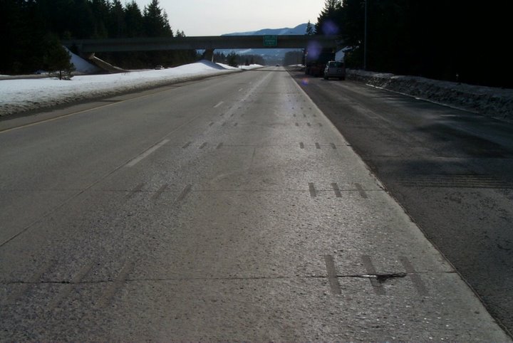
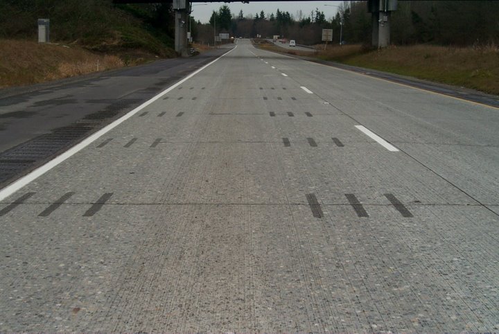
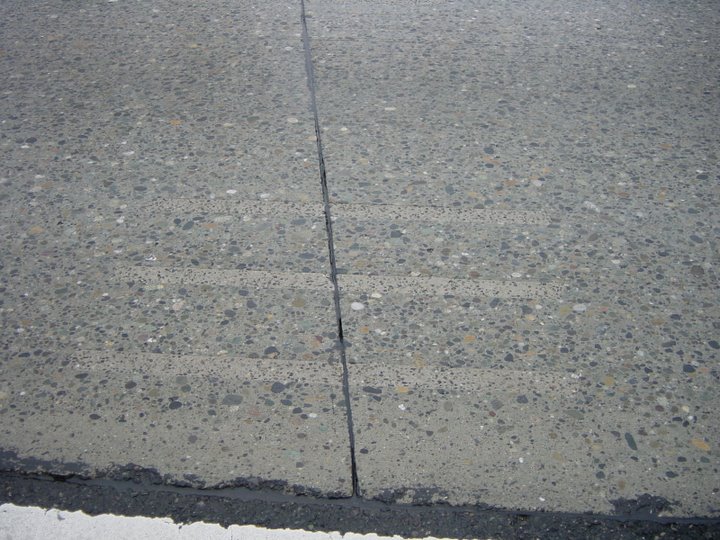
Figure 84 and Figure 85 illustrate successful completion of the dowel bar retrofit process.

