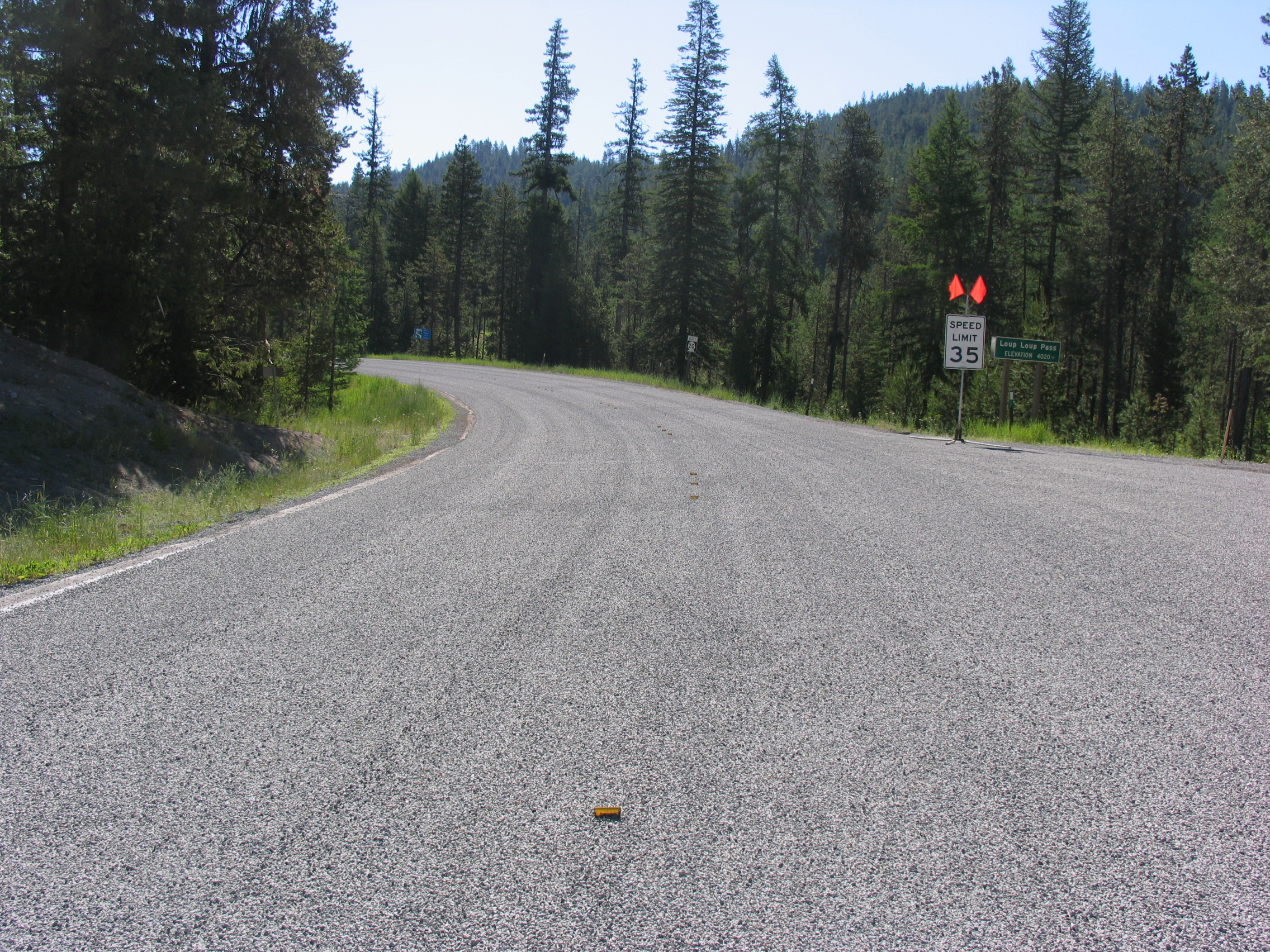
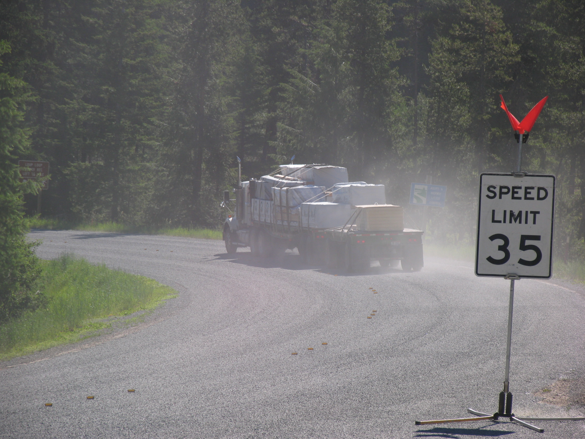
A bituminous surface treatment (BST), also known as a seal coat or chip seal, is a thin protective wearing surface that is applied to a pavement or base course. BSTs can provide all of the following:
- A waterproof layer to protect the underlying pavement.
- Increased skid resistance.
- A filler for existing cracks or raveled surfaces.
- An anti-glare surface during wet weather and an increased reflective surface for night driving.
Historically, BSTs have been in use since the 1920s, primarily on low volume gravel roads. BSTs are increasingly in use as a preventative maintenance procedure on flexible pavements of good structure.
Purpose
A BST offers preventive maintenance from the effects of sun and water, both of which may deteriorate the pavement structure. BSTs create a new wearing course, as well as a waterproof covering for the existing pavement. A BST makes it more difficult for water to enter the base material, and preventing freeze thaw damage for those locations with below freezing temperatures.
BSTs also increase the surface friction of the pavement, due to the addition of the cover aggregate. This combats the effects of raveling, which can make the pavement slippery and stopping difficult. A BST gives good, gripping texture to the pavement surface.
BSTs should be applied to a distress-free to moderately distressed pavement surface. A two to four year service life is common, while five year service lives are achievable.
Materials
BSTs are created using two main materials: asphalt and a cover aggregate.
Asphalt
Asphalt (as asphalt binder, cutback asphalt or asphalt emulsion) and aggregate (uniformly graded).
The asphalt is typically an emulsion. Care must be taken with the weather on the day of construction – ideally, a warm day with low humidity is preferred. BSTs should never be constructed on rainy days or when rain is predicted. Rain can dilute the asphalt binder if it has not yet cured, bringing the binder to the top of the cover aggregate; after the water evaporates, tires can pick up the loose aggregate or track binder across the surface.
Cutback Asphalt
While cutback asphalt is historically an option for BSTs, the solvent used (usually gasoline or kerosene) is expensive and potentially dangerous. A cutback is asphalt dissolved in a solvent, allowing the asphalt to be pumped and sprayed without heating it to high temperatures. The solvent evaporates into the surrounding air, leaving the asphalt binder. Once the solvent has completely evaporated, the cutback has cured. Fast setting time cutbacks use gasoline, while kerosene is used for longer curing times.
Cutback asphalt usage has declined in recent years due to pollution and health concerns.
Asphalt Emulsion
Today, asphalt emulsions are more commonly used. An emulsion consists of an oil suspended in water. In this case, the asphalt cement is the oil component. A surfactant (also called an emulsifying agent) needs to be added in order to make the oil and water mix. Having the asphalt suspended in water allows the placing temperature for a BST to be significantly lower than for a hot mix asphalt.
A surfactant offers two benefits – one, it causes asphalt to form tiny droplets that will suspend in water by lowering the surface tension between the asphalt and the water. Two, a surfactant determines the electrical charge of the emulsion. Aggregate will have an electrical charge, usually negative. Since opposite charges will attract, it is important to choose an emulsion with the opposite charge, which will enhance the binding of the asphalt to the aggregate. Cationic (having a positive charge) emulsions are typically used.
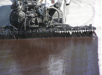
The next largest (by volume) ingredient in an asphalt emulsion is the water. Water forms approximately one-third of the volume of the emulsion. Asphalt particles will, with the help of the emulsifying agent, suspend in the water. It is important to note that if the emulsion breaks (when the asphalt and water separate from one another) the emulsion will change from brown to black. The aggregate must be applied and rolled before the emulsion breaks. When the emulsion breaks, the water evaporates, and the asphalt remains on the roadway.
The asphalt cement is the primary ingredient in a BST. This asphalt is much like the asphalt used in hot mix paving. Sometimes, a latex or polymer modified asphalt may be used to improve early chip retention or BST durability.
Aggregate
Aggregates typically used include natural gravel or crushed stone. These must be clean and dust free, hard, and uniform. This is to provide a durable surface for traffic. It is common to limit the percent of material passing the No. 200 sieve (0.075 mm) to about 1 percent or less since excessive dust can be a serious adhesion issue for BSTs.
Aggregate used in construction of a BST should be placed only one layer thick. The exceptions to this is when adding chokestone or a second BST layer (a two layer BST is often referred to as a “double shot” treatment). Placing too much aggregate will cause aggregate pickup, whereby the well placed stones are dislodged, and may cause automobile windshield damage.
A small amount of excess aggregate, more than 5% but less than 10%, may be placed in turning and stopping zones. This will reduce tire scuffing in the freshly laid BST.
Aggregate Shape
Aggregate shape can be described as either flat or cubical. It can also be either round or angular. These qualities will effect the seal coat in different ways.
If an aggregate is flat, the BST will lose chips excessively in the non-wheelpath section of the road bed, or it may bleed in the wheelpath. This is due to the pressure from automobile tires causing the flat chips to settle into the asphalt on their flattest side. The BST then becomes thinner where the tires pass over. Aggregate with a Flakiness Index of 20% or lower should be used for high volume roadways.
Flakiness is not an issue in low volume applications, as many tire passes are needed in one area to cause this phenomenon. However, for most applications, cubical aggregate is preferred due to its stability.
Round aggregate is likely to roll and become displaced by traffic. Angular aggregates lock to one another. Areas with frequent snow plowing must take extra care in order to make sure a BST with a round aggregate will embed properly as the snow plow may shave off the taller pieces of stone.
On high volume roads, a double chip seal may be the better option. This is when a BST is placed atop another one. The aggregate on the bottom layer should be about twice as large as the one on the top. The smaller stones on top will be less likely to cause windshield damage and the surface is typically smoother than a single seal coat.
Aggregate Size
Aggregate gradation and size are important to the success of a BST. Gradation describes the distribution of large and small stones within the aggregate mix. For a BST, the two options are one-size aggregate or graded aggregate.
One-size aggregate is an aggregate mix that comprises roughly equal sized stones. If all the aggregate is approximately the same size, there are good void spaces for the asphalt to fill and adhere the stones to the pavement structure. Other benefits of one-size aggregate include good friction between the surface and vehicle tires due to maximizing tire-aggregate contact area, good drainage between stones, and simplicity in determining whether the amount of aggregate is sufficient.
Graded aggregate simply means that the aggregate has some distribution in size. There are many types of gradations, as in dense graded or gap graded. One difficulty that may arise from using graded aggregate is that the lower air voids in graded aggregate means that the binder may not fit between chips. Problems from bleeding to aggregate loss may occur.
Aggregate containing dust must ‘‘not’’ be used for a BST. Dust will prevent the aggregate from bonding to the asphalt binder and will create problems with excessive chip loss. One of two solutions to this problem may be used: either use a high float emulsion, which has wetting agents that assist with bonding in dusty aggregate, or wash the aggregate with clean potable water and then air dry.
Design
Design of BSTs must take into consideration all of the points mentioned in the Asphalt and Aggregate sections of this article. Material must be of good quality and the correct properties.
The design must also take into consideration the amount of binder and cover aggregate to apply. In order to prevent excessive chip loss, about 70 percent of the aggregate (and a minimum of 50 percent) must be embedded in the residual asphalt – the asphalt left after the water or cutback has evaporated. With an asphalt emulsion, the binder must rise near to the top of the aggregate, otherwise the residual asphalt will be insufficient to properly embed the aggregate. The goal is to have the binder at about 70% of the chip height after the binder has cured.
One procedure which is commonly used is the McLeod Design Procedure. For more information on this, please refer to the Minnesota Seal Coat Handbook.
|
|
Distressed Pavement
Surface distress is “Any indication of poor or unfavorable pavement performance or signs of impending failure; any unsatisfactory performance of a pavement short of failure” (Highway Research Board, 1970[1]). Surface distress modes can be broadly classified into the following three groups:
- Fracture. This could be in the form of cracking (in flexible and rigid pavements) or spalling resulting from such things as excessive loading, fatigue, thermal changes, moisture damage, slippage or contraction.
- Distortion. This is in the form of deformation (e.g., rutting, corrugation and shoving), which can result from such things as excessive loading, creep, densification, consolidation, swelling, or frost action.
- Disintegration. This is in the form of stripping. raveling or spalling, which can result from such things as loss of bonding, chemical reactivity, traffic abrasion, aggregate degradation, poor consolidation/compaction or binder aging.
Thus, surface distress will be somewhat related to roughness (the more cracks, distortion and disintegration – the rougher the pavement will be) as well as structural integrity (surface distress can be a sign of impending or current structural problems).
Pavement must be repaired prior to the application of a BST.
Pavement can be tested in order to help determine what repairs should be made. Common tests include wheelpath rutting, roughness, and surface friction. If structural failure is suspected, a falling weight deflectometer test may be conducted.
Distress Correction
Once the pavement structural distress has been quantified, the distress must be corrected before constructing a BST.
Base Repair
If the distress is so severe that the subgrade has been affected, the structure must be replaced through a full-depth dig-out, which may be done in a variety of ways. The designer must specify the area and depth of the repair for each section of the pavement.
Patching
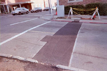
Patching may be done (in HMA, in PCC) to repair wheel ruts, edge raveling, and delaminated or pothole areas. Common construction practices in placing HMA for patching include use of a spreader box, grader/blade patching, or using a paver. Results from using any of these methods will be satisfactory if they are properly performed. To avoid chip loss, all paved repair areas must be fog sealed prior to applying BST. Fog sealing is the light application of an asphalt emulsion.
Fog seals can also be placed on a new chip seal after the final brooming to assist in aggregate retention and prevent the shedding and shelling of the new aggregate. The fog seal gives an additional layer of waterproofing to the new wearing course. In this type of use, the fog seal should be applied 3 to 14 days after the chip seal was placed, with brooming to be completed immediately before the fog seal is placed.
Crack Sealing
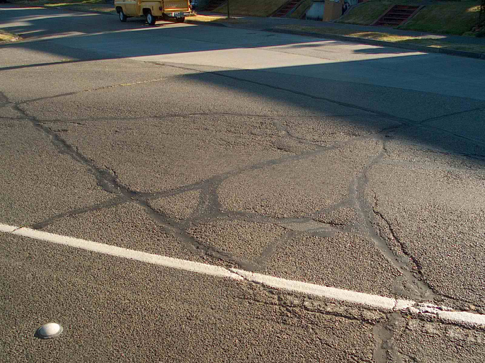
Crack seals are used for repairing transverse and longitudinal cracks. This is typically the use of a rubberized tar material or mixture of sand and asphalt emulsion to fill the crack. Cracks and joints 1/4″ or greater should be cleaned of any incompressible material including old sealant, and then sealed prior to applying a BST.
Slurry Seal
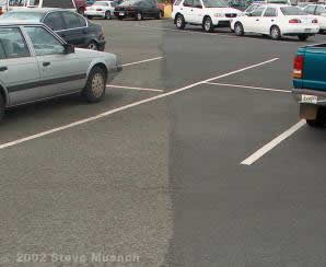
A slurry seal ought to be applied at 25% of the design life for maximum benefit in preserving the pavement structure. Maintenance with a slurry seal must be instituted before significant pavement deterioration occurs. Aggregate size, emulsion type, and any additives determine classification of the slurry seal. If distress is noted, crack sealing ought to be done before applying a slurry seal. When a slurry is placed over dry and raveling pavement, a tack coat should be done before the slurry seal.
Construction
A single layer BST is constructed in the following steps:
- Surface preparation. Surface defects, such as potholes, are repaired and the existing surface is cleaned (e.g., by a street sweeper).
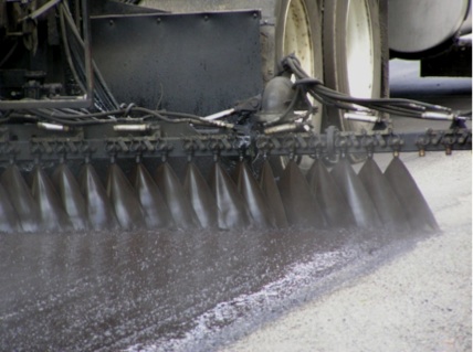
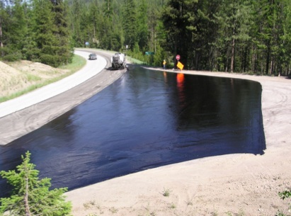
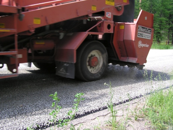
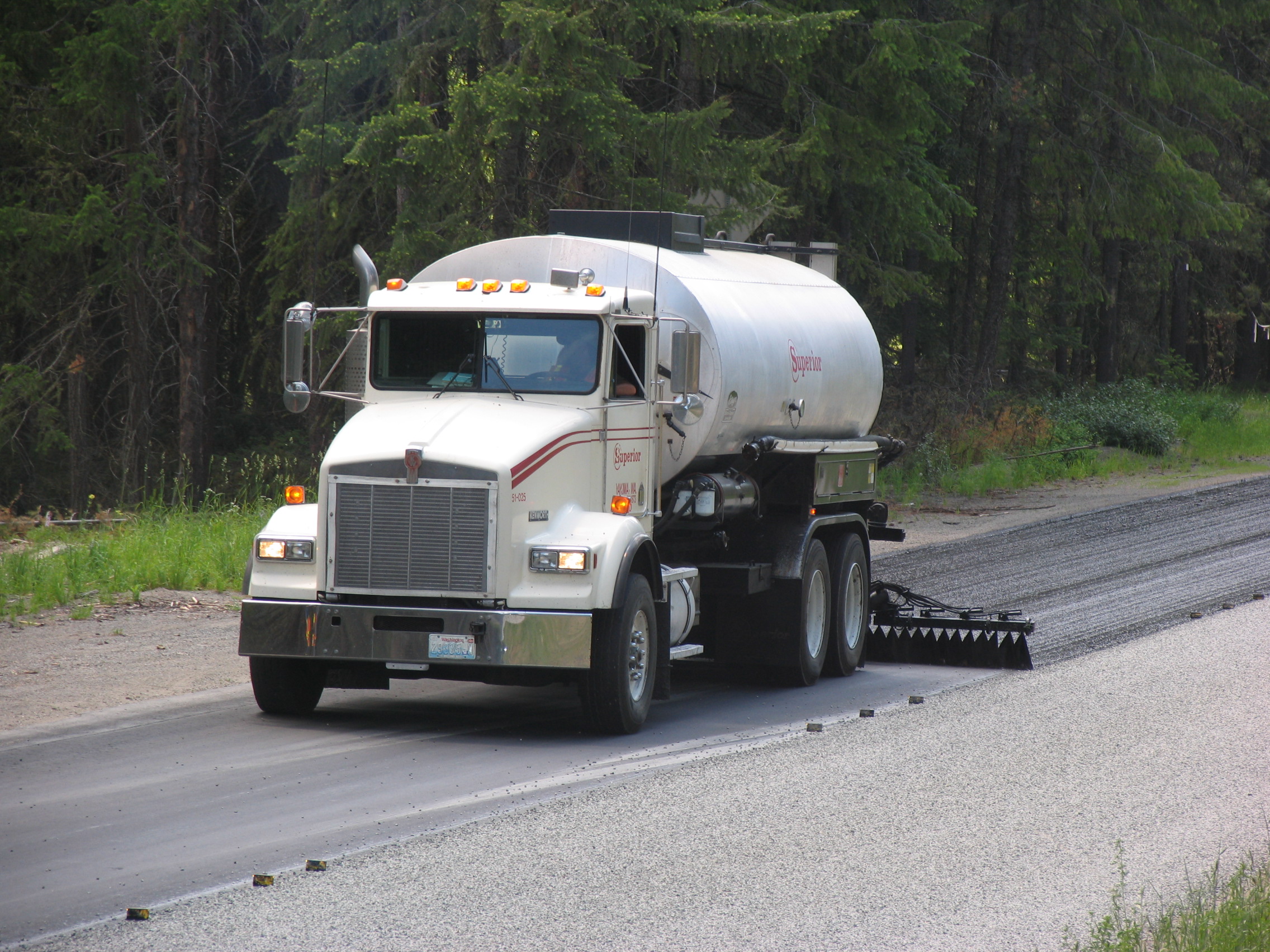
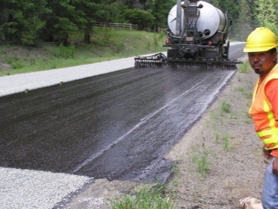
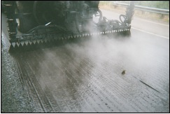
- Asphalt material application. Typically, an asphalt emulsion is applied from a spray truck to the surface of the existing pavement (see Figure 1).
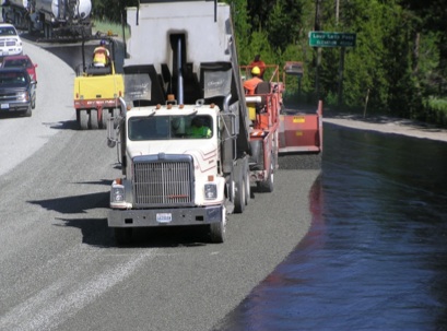
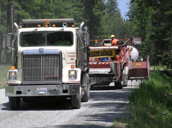
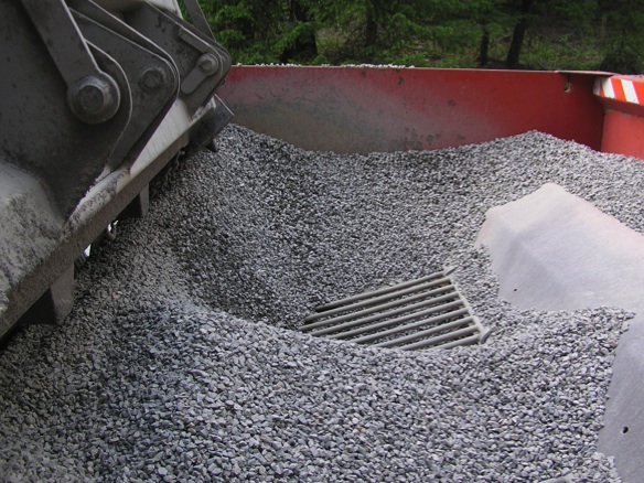
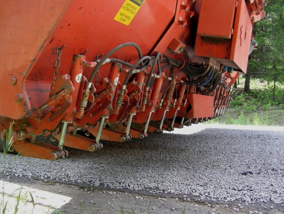
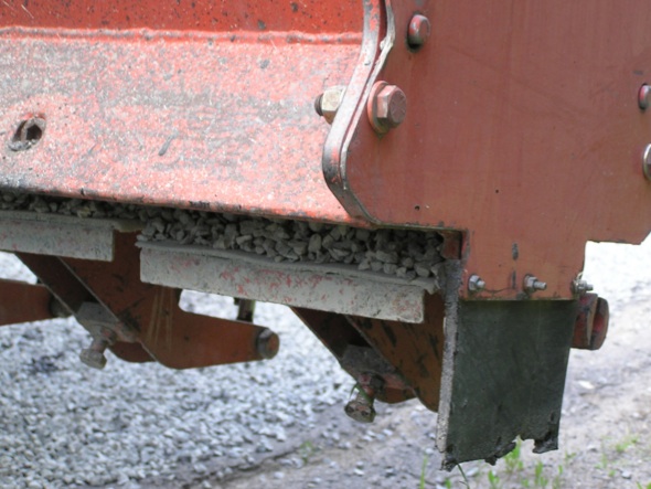
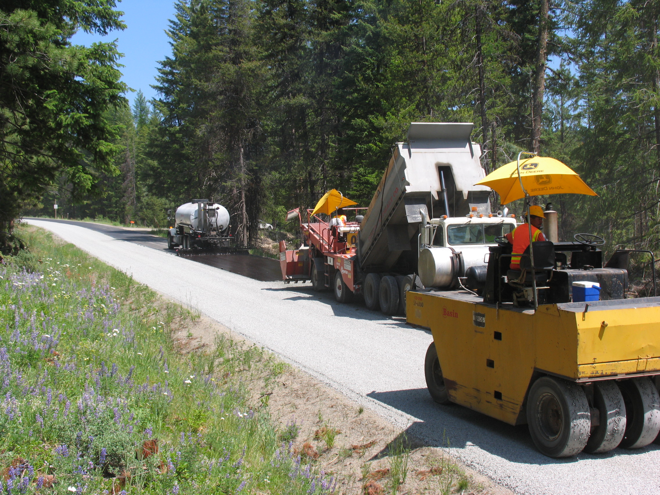
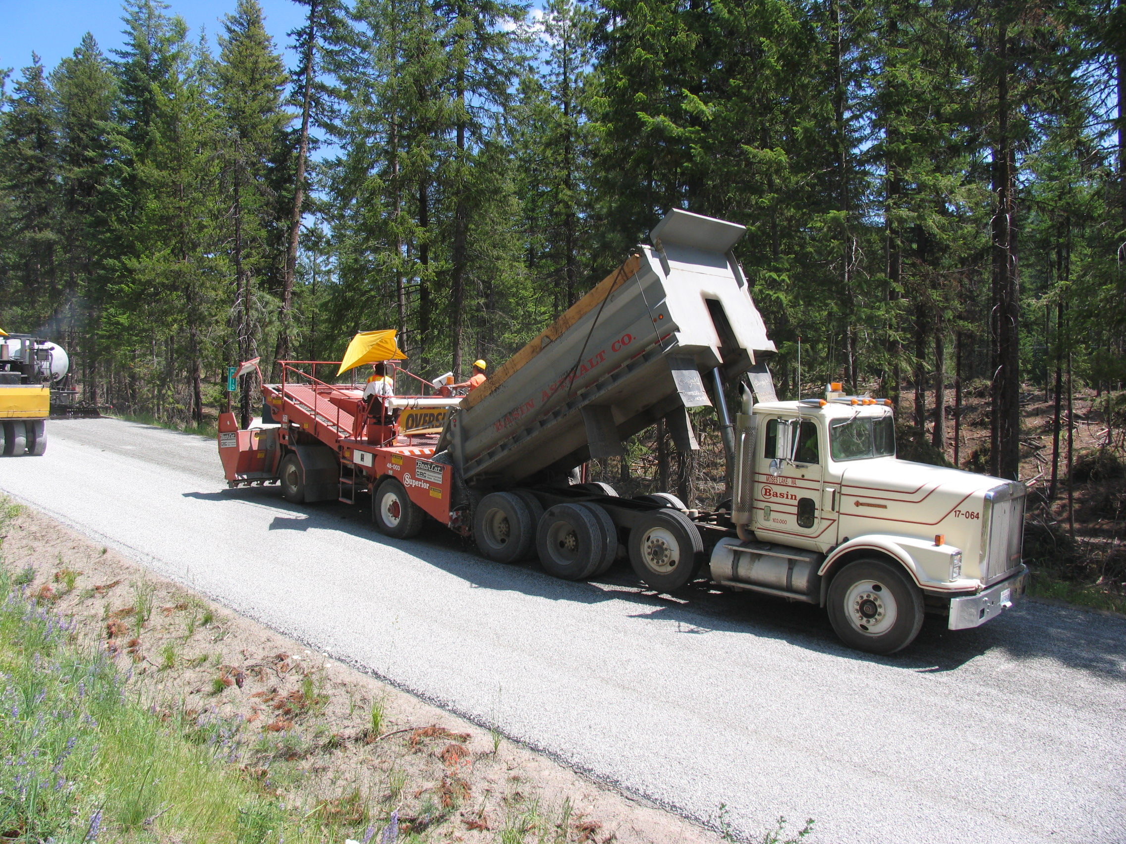
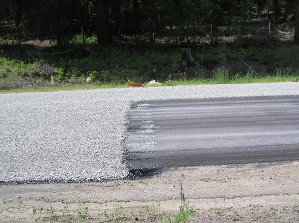
- Aggregate application. A thin aggregate cover (only one stone thick) is spread over the asphalt material before it has set (see Figure 2). The aggregate usually has a uniform gradation.
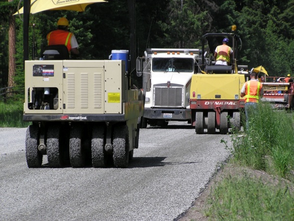
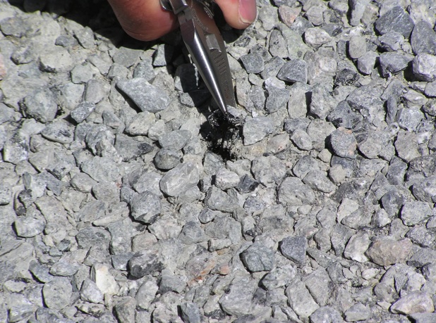
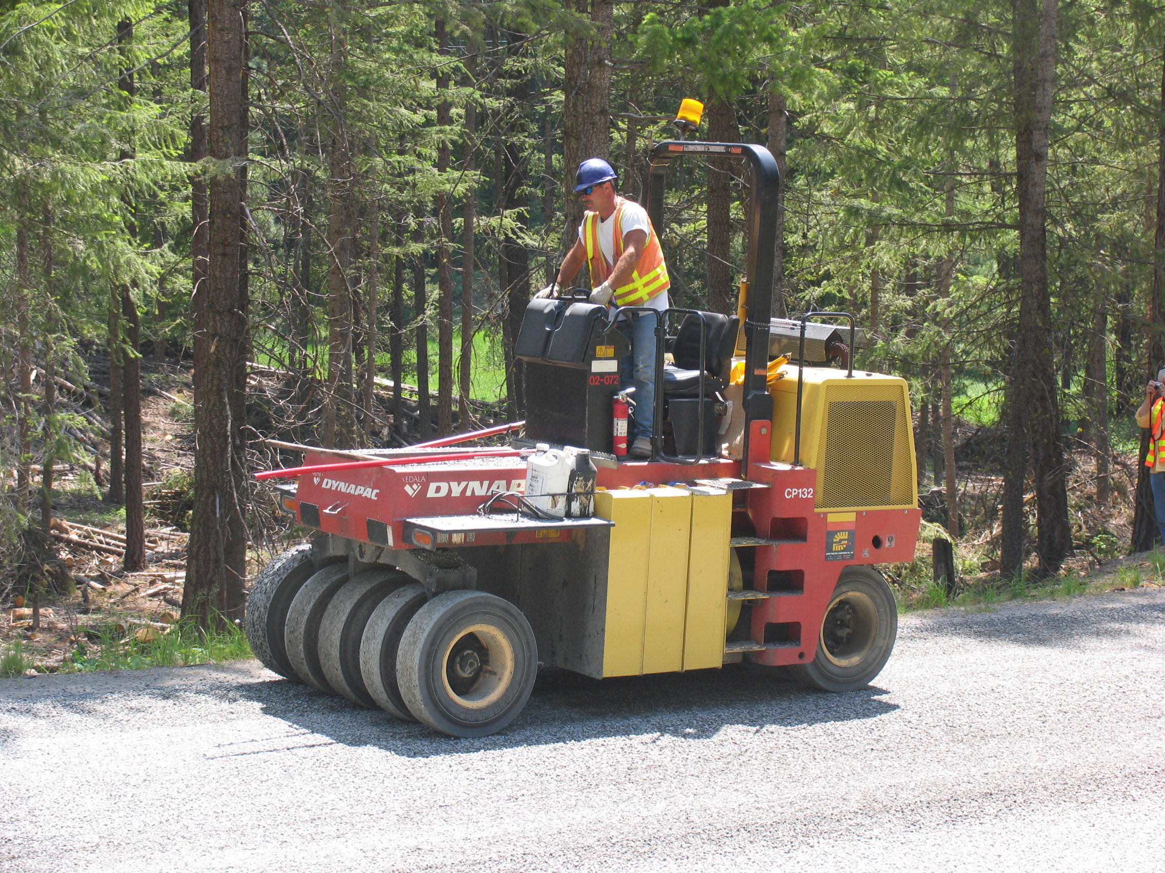
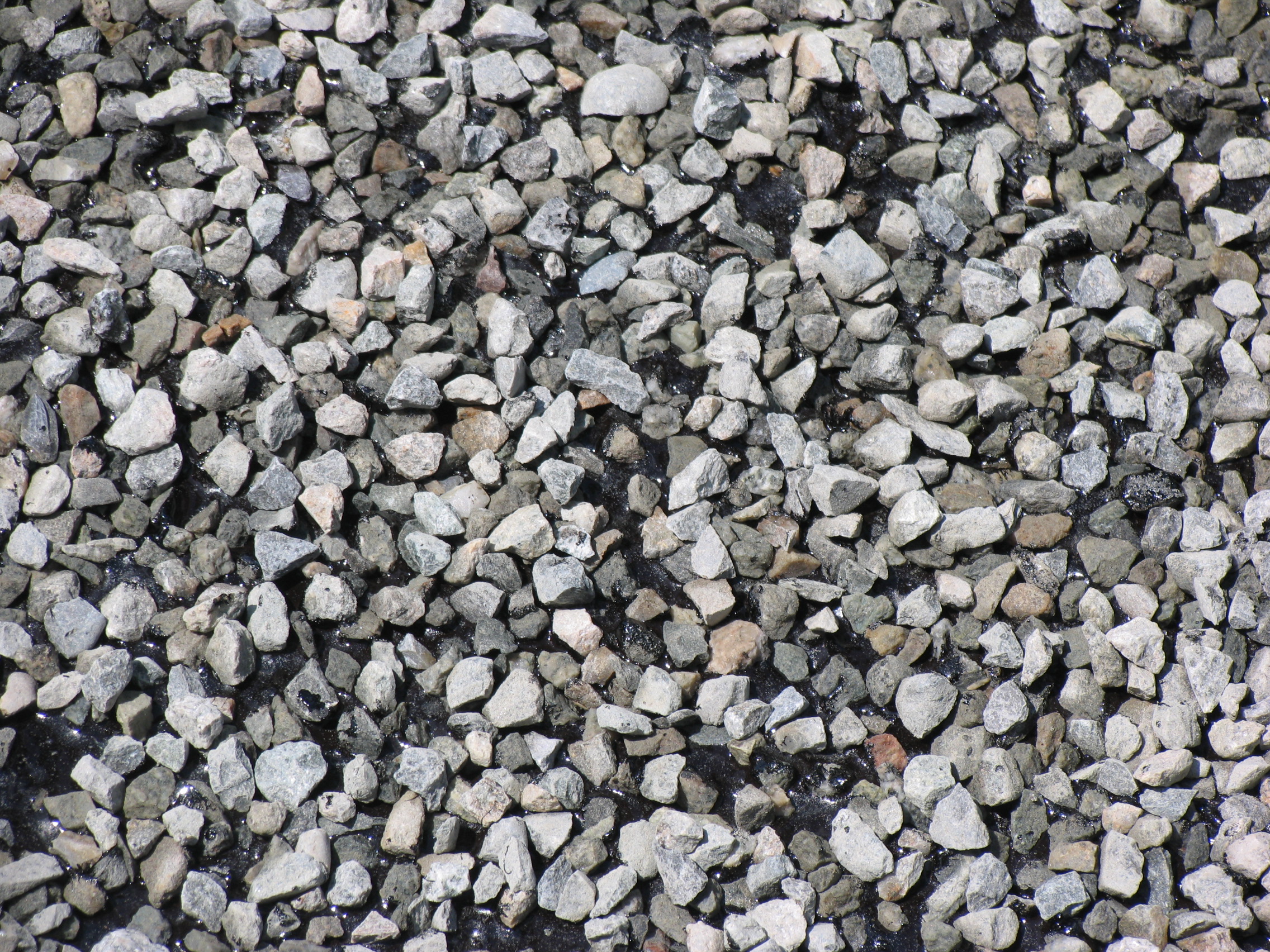
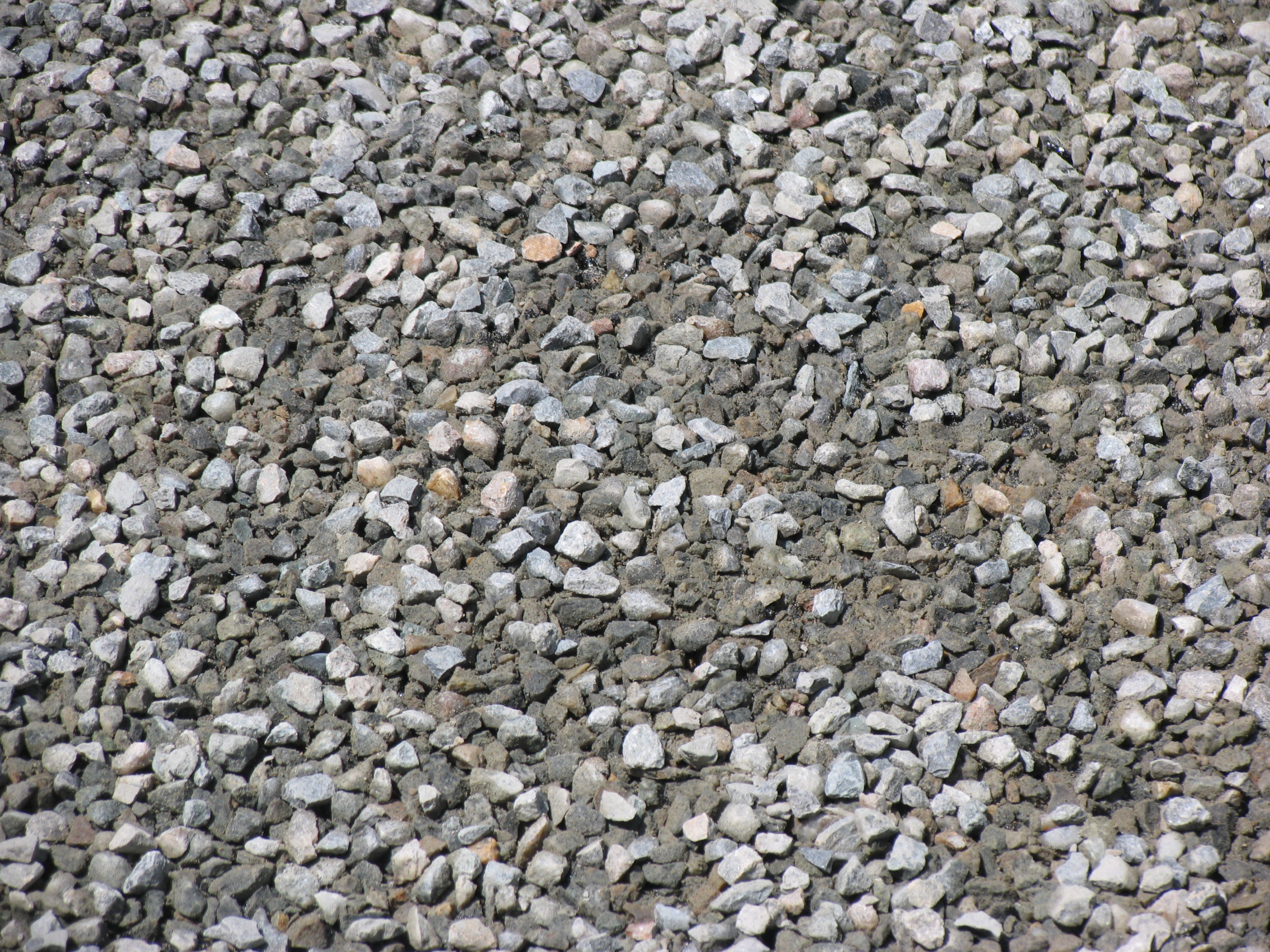
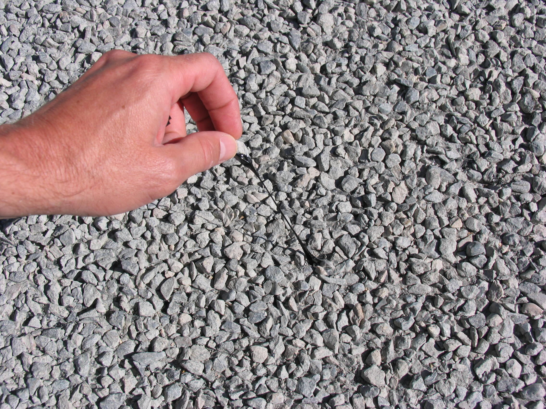
- Aggregate embedding. A roller (usually a pneumatic tire roller) is used to push the aggregate into the asphalt material and seat it firmly against the underlying pavement (see Figure 3). Generally, about 50 percent of each aggregate particle should be embedded in the asphalt material (see Figure 4) after final rolling. About 70 percent of each aggregate particle will be embedded after several weeks of traffic. It is common to place an aggregate “chokestone” on top of the uniformly graded larger aggregates after embedment. Chokestone is essentially a finer aggregate gradation (e.g., less than 12.5 mm (1/2 inch)) used to make a more dense aggregate matrix at the level of embedment (see Figure 5). This more dense matrix helps prevent excessive aggregate loss due to traffic.
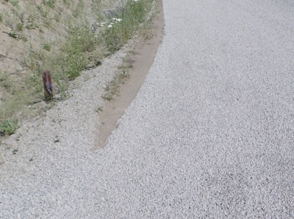
Multiple layer surface treatments are done by repeating the above process for each layer. Figure 9 shows a BST in Washington State.
Making Construction Joints
Construction joints are needed on any project that takes more than one day to complete. In order to make the joint sound and level with the previous day’s construction, special practices must be used for the construction joint. These steps are laid out in the following images.
|
|
|
|
|
|
Troubleshooting
BST construction depends on many factors, as mentioned in the prior sections of this article; among them are aggregate structure and gradation, binder grade and electrical charge, design process, traffic volume, and pavement structure condition. There are many other considerations which cannot be covered in the scope of this article, including specific construction methods and equipment used.
Common problems include loss of cover aggregate, streaking, bleeding or flushing, and utility connections in the pavement.
Loss of cover aggregate
Loss of the aggregate cover is probably the most common problem with a BST. This may be due to poor gradation, dusty aggregate, binder breaking before aggregate is laid, poor rolling of the centerline seam, and insufficient asphalt binder.
Typical solutions to these problems are to apply more asphalt binder so that the cured binder reaches 70% of the height of the aggregate. This is called the residual asphalt. Also, a clean, dust free aggregate must be used to ensure proper asphalt binding.
Streaking
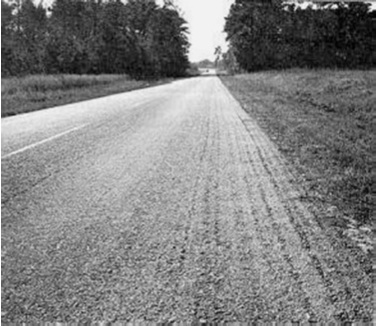
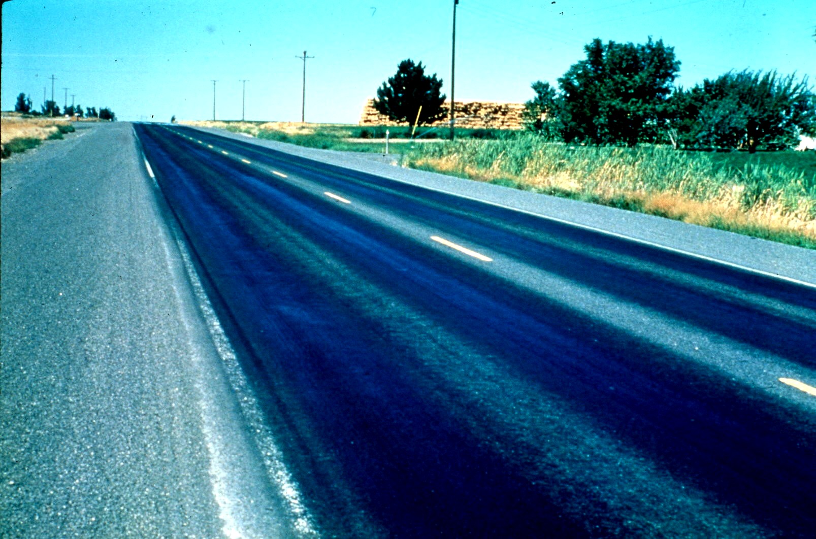
Streaking is when grooves or ridges are seen in the seal coat surface. This is an undesirable situation, however, it is primarily cosmetic. The asphalt binder distributor is the problem when observing streaking. Proper calibration of the distributor will ensure that streaking does not happen in the future.
|
|
|
Bleeding (also called flushing)
Bleeding is the term for excess asphalt binder in the wheelpath. Typical causes of bleeding are either applying too much binder, or using aggregate which is too flat.
The solutions to this problem are either to reduce the asphalt application rate to the proper amount (so that residual asphalt is 70% of the aggregate height) or to use a more cubic aggregate.
Utility connections
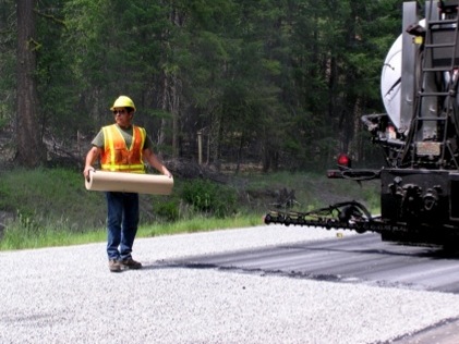
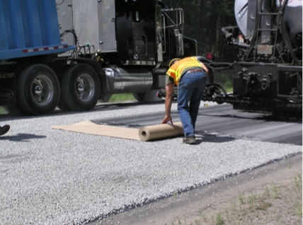
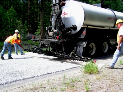
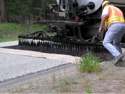
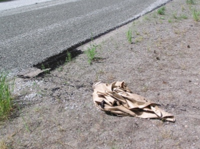
Manholes or gate valves may interrupt the surface of a pavement. However, it is undesirable to cover these important structures with the BST. These utility connections can be covered with kraft paper, roofing paper, or sand in order to prevent the binder from adhering to the utilities. These can be removed after the BST is applied to the remainder of the pavement structure and properly disposed of.
Other Info
Traditionally, BSTs were thought of as most applicable to low volume, low speed roads because they will eventually involve some amount of loose aggregate. On a high volume or high speed road, this loose aggregate can be picked up and thrown by wheels, which can result in chipped paint and broken windshields. However, developments in asphalt cement modifiers and BST construction procedures have made it possible to use them on high volume/speed roads including interstates.
NCHRP Best Practices
According to the National Cooperative Highway Research Program (NCHRP), there are 38 best practices that have been found in a literature review undertaken in 2003. The following is directly quoted from NCHRP Synthesis 342. When, in the following sections, various chapters are referenced, that is the document to use for further research.
Best practices in pavement selection, design, and material selection
- View chip seals as a preventive maintenance tool to be applied on a regular cycle to reinforce the pavement preservation benefits of the technology (chapter nine).
- Chip seals perform best on roads with low underlying surface distress that will benefit from this technology (chapter three).
- Chip seals can be successfully used on high-volume roads if the agency’s policy is to install it on roads before pavement distress becomes severe or the structural integrity of the underlying pavement is breached (chapter nine).
- Characterize the underlying road’s texture and surface hardness and use that as a basis for developing the subsequent chip seal design (chapter three).
- Try using the “racked-in seal” as the corrective measure for bleeding instead of the North American practice of spreading fine aggregate (sometimes called “chat”) on the bleeding surface (chapter three).
- Conduct electrostatic testing of the chip seal aggregate source before chip design to ensure that the binder(s) selected for the project is compatible with the potential sources of aggregate (chapter five).
- Use life-cycle cost analysis to determine the benefit of importing either synthetic aggregate or high-quality natural aggregates to areas where the availability of high quality aggregate is limited (chapter five).8. Specify a uniformly graded, high-quality aggregate (chapter five).
- Consider using lightweight synthetic aggregate in areas where post-construction vehicle damage is a major concern (chapter five).
- Use polymer-modified binders to enhance chip seal performance (chapter five).
- Recognize that both hot asphalt cement and emulsified asphalt binders can be used successfully on high-volume roads. The selection of binders modified by polymers or crumb rubber seems to reinforce success (chapter nine).
Best practices in contract administration, warranties, and performance measures
- Award chip seal contracts in time to permit early season construction (chapter four).
- Time the letting of the contract to allow sufficient time for the curing requirements of preconstruction pavement preparation activities (chapter four).
- Package chip seal contracts in jobs large enough to attract the most qualified contractors (chapter four).
- In-house maintenance personnel are best used to install chips seals in areas where the greatest care must be taken to achieve a successful product (chapter nine).
- Use warranties for chip seal projects only when the contractor is given the latitude to determine the final materials and methods used to achieve a successful chip seal (chapter four).
- The sand patch method to measure chip seal macrotexture can serve as an objectively measured chip seal performance indicator (chapter eight).
- The use of the chip seal deterioration model expressed in the New Zealand P17 specification can furnish an objective definition of chip seal performance based on engineering measurements (chapter eight).
- The two previously described practices can be supplemented with continued visual distress rating based on the Ohio DOT chip seal performance criteria shown in the text in Table 13 (chapter eight).
Best practices in construction
- For optimum performance, apply all types of chip seals in the warmest, driest weather possible, for optimum performance (chapter seven).
- Ambient air temperature at the time of application should be a minimum of 50°F (10°C) when using emulsions, and 70°F (21°C) when using asphalt cements, with a maximum of 110°F (43°C) (chapter seven).
- When using emulsions, the temperature of the surface should be a minimum of 70°F (21°C) and no more than 140°F (54°C) (chapter seven).
- Complete patches at least 6 months before and crack seals at least 3 months before the application of chip seals (chapter seven).
- Variable nozzles permit the application of a reduced rate of binder in the wheelpaths and help combat flooding in the wheelpaths, a defect that makes chip seals prone to bleeding. Conversely, the Australian use of prespraying is another method for adjusting the transverse surface texture of a pavement surface before applying a chip seal (chapter seven).
- A drag broom fitted on those rollers doing the initial roller pass corrects minor aggregate spread deficiencies such as corrugation, uneven spread, or missed areas (chapter seven).
- Apply the aggregate as quickly as possible to both emulsified and hot asphalt binders (chapter seven).
- The Montana field-sweeping test curtails the bias to spread excess aggregate created by a unit-price contract (chapter seven).
- Have the most experienced inspector predrive each shot and paint binder rate adjustments on the pavement to facilitate field rate adjustments (chapter seven).
- In areas where extensive stopping and turning movements take place, the application of a small amount of excess aggregate may reduce scuffing and rolling. The use of a racked-in seal may be a viable engineered solution for determining the precise amount of aggregate for these problematic areas (chapter seven).
- Furnish and enforce rolling guidelines and specifications for roller coverage, rolling patterns, and minimum rolling time to achieve full lane coverage and a similar number of passes for all areas of the lane (chapter seven).
- The required number of rollers is a function of desired distributor production and required rolling time for each shot width on the project (chapter seven).
- Have rolling follow as closely as practical behind the chip spreader (chapter seven).
- Maintain traffic control for as long as possible to give the fresh seal the maximum amount of curing time (chapter seven).
Best practices in chip seal equipment and quality assurance and quality control
- Require chip seal contractors to use state-of-the-art equipment and to control the rolling operation to enhance chip seal success (chapter six).
- Use computerized distributors (chapter six).
- Require preproject analysis of the ability of the chip seal equipment spread to keep up with the production rate of the distributor (chapter six).
- Use variable nozzles to reduce the amount of binder that is sprayed in the wheelpaths (chapter six).
- Plastic bristles for rotary brooms minimize aggregate dislodgment during brooming (chapter six).
- An aggressive quality control testing program combined with close inspection generates chip seal success (chapter seven).
- Assign experienced personnel who understand the dynamics of chip seal construction as field quality control and quality assurance persons (chapter seven).
- Regularly calibrate both the distributor and the chip spreader (chapter seven).
- Evaluate aggregate–binder compatibility tests shown in the text in Table 12 for local appropriateness and use in the field (chapter seven).
- Field test both binders at the distributor and aggregate stockpiles to ensure that material has not degraded owing to handling during transportation (chapter seven).
Minnesota Seal Coat Handbook
The Minnesota Department of Transportation (Mn/DOT) has concluded a research study on the proper techniques involved in seal coating. A key part of the research project involved performing seal coat designs using the procedure developed by Norman McLeod. In addition, research personnel were present on many seal coat construction projects assisting the inspector and contractor. The primpary purpose of this handbook, updated in 2006, is to provide a solid background in seal coat materials, equipment, design and construction for the field inspector. Divided into two main sections, this updated handbook provides direction for designers and field personnel. This project was sponsored by the Minnesota Local Road Research Board
Download the Handbook here
In 2007, Tom Wood instructed a Seal Coat class based upon the Minnesota Handbook at the Transportation Learning Network, one of the main programs of the Upper Great Plains Transportation Institute at North Dakota State University.
Surveys
Bridge Deck Chip Seal Survey, March 2001
Questions
- Have you used Chip Seals on Concrete Bridge Decks?
- Comment
- State Name
Results
Bridge Deck Chip Seal Survey by WSDOT
- Highway Research Board. (1970). Special Report No. 113: Standard Nomenclature and Definitions for Pavement Components and Deficiencies. Highway Research Board, National Academy of Sciences, Washington, D.C.↵

